
Operating instructions


Status Reporting
83
5
Status Reporting
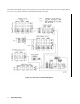
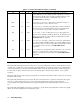
This chapter discusses the status data structure of the electronic loads as shown in Figure 5-1. The Standard Event Status
register group, the Output Queue, and the Status Byte and Service Request Enable registers perform standard GPIB
functions and are defined in IEEE 488. 2 Standard Digital Interface for Programmable Instrumentation. Other status
register groups implement the status reporting requirements of the electronic load. The Channel Status and Channel
Summary groups are primarily used by multiple electronic loads. This is because each channel in a multiple electronic
load has its own Status register to provided status information for that channel.
General Register Model
The Condition register represents the present or “live” state of various electronic load signals. Reading the Condition
register does not change the state of its bits. Only changes in electronic load conditions change the contents of this
register. Not all status register groups have a Condition register. In some cases, such as the Standard Event Status
registers, conditions are directly input into an Event register. In other cases, such as the Channel Summary registers,
summary information from other registers is directly input into an Event register.
The Event register captures changes in conditions. Each bit in an Event register either corresponds to a condition bit in a
Condition register, or to a specific condition in the electronic load. An event becomes true when the associated condition
makes one of the following electronic load-defined transitions:
•
Positive TRansition (0-to-1)
•
Negative TRansition (1-to-0)
•
Positive or Negative TRansition (1-to-0 or 0-to-1)
The PTR/NTR filters determine what type of condition transitions set the bits in the Event register. Only the operation
Status registers allow transitions to be programmed. All other register groups use an implied 0-to-1 condition transition to
set bits in the Event register. Reading an Event register clears the register (all bits set to zero). When the electronic load
is turned on, Event registers are set to zero, and the PTR/NTR filters are set to their firmware assigned states.
The Enable register selects which bits in the corresponding Event register are logically-ORed into the Summary bit. At
turn-on, Enable registers are set to zero. However, the Standard Event Enable register and the Service Request Enable
register are not set to zero if the *PSC command is programmed. These registers are set to the most recent values saved in
non-volatile memory before the Electronic Load was last turned off.
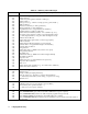
Channel Status
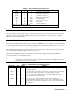
The Channel Status registers inform you that one or more channel status conditions, which indicate the presence of certain
errors or faults, have occurred on a specific channel. Table 5-1 describes the channel status conditions that apply to the
electronic load.
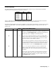
The Channel Status Condition register represents the present status of a channel; the bits are set when the indicated
condition is true.
The Channel Status Event register records all of the channel conditions that have occurred since the last time this register
was read. A condition transition from 0-to-l on a bit in the Channel Status Condition register will set the corresponding bit
in the Channel Status Event register. Reading the Channel Status Event register resets it to zero.