
Operating instructions

Language Dictionary
37
*SAV Save Command
Type
Device State
Description
This command stores the present state of the single electronic load and the states of all
channels of the multiple electronic load in a specified location in memory. Location 0 is in
nonvolatile memory and retains its state throughout power cycling. The electronic load will
be set to the state in location 0 at power turn-on. If no state has been saved to location 0,
then it will still contain the factory-default state (refer to “Factory Default Settings” in the
Operating Manual of the electronic load model that you are programming). States stored in
locations 1 through 6 are lost whenever power is cycled.
Note
To restore the factory-default state to Location 0, execute *RST;*SAV 0
The parameters stored by *SAV are identical to those affected by *RST except that the
following states are not stored:
■ CAL:MODE ON|OFF (Refer to the electronic load; Operating Manual).
■ CHAN.
Note
*SAV also does not store the states of Status Enable registers or Transition Filters.
Command Syntax
*SAV <NRf>
Parameters
0 to 6
Suffix
None
Example
*SAV 2 Save the present state of the electronic load to location 2
Related Commands
*RCL *RST
*SRE Service Request Enable Command/Query
Type
Device Interface
Description
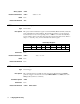
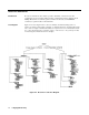
This command sets the condition of the Service Request Enable register, which determines
which events of the Status Byte register (see *STB) are allowed to set the MSS (Master
Status Summary) bit. A “1” in the bit position enables the corresponding Status Byte bit to
set the MSS bit. All the enabled bits are logically ORed to cause Bit 6 (the Master
Summary Status Bit) of the Status Byte register to be set. See Chapter 5 - Status Reporting
for more details concerning the Status Byte register.
Command Syntax
*SRE <NRf>
Parameters
0 to 255
Suffix
None
Example
*SRE 20 Enables either the CSUM or MAV condition to cause a service request.