PROGRAMMING MANUAL Agilent Technologies Electronic Load Family Agilent Part No. 06060-90005 Microfiche Part No.
PRINTING HISTORY The manual printing date and part number indicate the current edition. Reprints between editions will have the same printing date and may include change pages with corrections or additions to be made to the manual by the user. New editions of this manual will have a new printing date and, in some cases, may have a new part number. The new edition will include all changes and corrections made since the previous edition.
CONTENTS 1. Introduction Purpose .........................................................................................................................................................7 Documentation .............................................................................................................................................7 Supplied.....................................................................................................................................................
CONTENTS (continued) 4. 4 Language Dictionary Introduction ................................................................................................................................................29 Keywords ................................................................................................................................................29 Parameters .........................................................................................................................................
CONTENTS (continued) RES:TLEVel ...........................................................................................................................................58 Status Subsystem........................................................................................................................................59 Syntax Diagram.......................................................................................................................................60 STAT:CHANnel...................
1 Introduction Purpose The purpose of this guide is to enable you to use HPSL commands to remotely control your Agilent Technologies electronic load from a controller using HPSL programming language. It is assumed that the following has been done: • The electronic load has been installed and is operating normally from its front panel. • The controller has been connected to the electronic load and the electronic load’s GPIB address has been set.
How To Use This Guide Chapter 2 - Introduction to HPSL Synopsis The basics of HPSL to help you understand the terminology and diagrams in Chapter 4. 3 - Introduction to Programming How to understand the command tree diagram and construct typical operating programs. 4 - Language Dictionary An alphabetically ordered description of all electronic load HPSL commands. 5 - Status Reporting An explanation of how the electronic load status registers are affected by the HPSL programming statements.
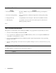
GPIB Capabilities Table 1-1. GPIB Capabilities of Electronic Loads Response Interface Function Talker/Listener All electronic load functions except for setting the GPIB address are programmable over the GPIB. The electronic load can send and receive messages over the GPIB. Status information is sent using a serial poll. Front panel annunciators indicate the present GPIB state of the electronic load. AH1, SH1, T6.
2 Introduction To HPSL What Is HPSL? HPSL is a system programming language developed by Agilent Technologies for controlling instrument functions. HPSL is intended to function with standard GPIB hardware. HPSL conforms to the IEEE 488.2 Standard Digital Interface for Programmable Instrumentation. This standard provides codes, formats, protocols, and common commands not defined in the original IEEE 488.1 standards.
Compound Command Queries When two or more keywords are connected by colons and followed by a question mark, it creates a compound query statement. VOLT:TRIG? Compound command queries CURR:PROT? MEAS:POW? HPSL Keywords Keywords (also known as “Instrument Control Headers”) are recognized by the electronic load's decoder, or “parser”. Each keyword is intended to be descriptive of the statement function.
Keyword Parameters Parameters are data values that the parser expects to find after certain keywords. All data programmed to or returned from the electronic load is ASCII. The data may be numerical data or character strings. HPSL uses the parameter forms in Section 7 of IEEE 488.2 Standard Digital Interface for Programmable Instrumentation with the additions described here. Numerical Data Formats HPSL accepts the first four numerical data types listed in Table 2-1 and described in Section 7 of IEEE 488.
Multiplier 1E6 1E3 1E-3 1E-6 1E-9 Note Table 2-3. Most-Used Suffix Multipliers Mnemonic Definition MA mega K kilo M milli U micro N nano You may construct compound suffixes of multipliers and elements. For example: 1 KHz for 1000 Hz; 1 A/µs for 1000000 A/s. Numerical Data Conventions. In this guide, numerical data types are shown in emphasized text within angle brackets, such as < NR1 > or < NRf > . On drawings, numerical data appears within boxes . .
Program Line Terminators. A terminator informs HPSL that it has reached the end of a statement. Normally, this is sent automatically by your GPIB programming statements. The termination also occurs with other terminator codes, such as EOI. In this guide, the terminator is assumed at the end of each example line of code. If it needs to be indicated, it is shown by the symbol < nl >, which stands for “new line”' and represents the ASCII coded byte 0A hexadecimal (or l0 decimal).
3 Introduction To Programming Types Of Commands and Queries The electronic load responds to two types of commands and queries, Common and Root. Common commands were introduced in Chapter 2-Introduction to HPSL and are relatively simple to use. The root commands are organized in a hierarchy that is best shown via a command tree diagram. Understanding The Command Tree Figure 4-2 in Chapter 4-Language Dictionary is a tree diagram of all the root commands for the electronic load.
Note Ignore the meanings of these commands for now. All keywords are defined in the Language Dictionary and command functions are explained in the electronic load Operating Manual. Figure 3-1 shows the RESistance commands, which form a typical branch that forms a ’’subtree" of its own. You can see that the RESistance branch has three subbranches; LEVel, RANGe, and TLEVel.
but the parser assumes that the two implied keywords are there. For the same reason, you can query the immediate resistance value with: RES? Note When sending a query, do not enter a space between the keyword and the question mark. The newline character < nl > or EOI terminator sends the parser back to the root level. Many controllers automatically send this character at the end of each program output string.
RES MAX < nl > Note MAX and MIN are the maximum and minimum values allowed in the present operating mode of the electronic load. For the electronic load this generally means the limits within the present range. MAX and MIN may also be used with queries to find the maximum and minimum permitted settings of the present mode.
Figure 3-3. What the Semicolon Does Note There is no single command to move the parser back two colons. In example a above, backing up from Level 2 to Level 1 requires a return to the root. Getting Back to the Root To go from a command in one branch to a command in another branch, you must first return to the root. You can do this by: ■ entering a new-line character. This is symbolized by () and can be any control character that starts a new line, such as: ■ linefeed (LF).
Figure 3-4. Returning the Parser to the Root Implied Keywords Keywords shown within brackets, such as CURR[:LEVel], are implied keywords. If they are omitted, the parser will execute them automatically. How to Use Implied Keywords. Because [LEVel] is an implied keyword, the parser regards the following two commands as the same: CURR:LEV 30 CURR 30 Under most circumstances, implied keywords are optional and you may omit them as in the above example.
By inserting the implied keyword in RES:LEV .5; you allowed the parser to interpret the (;) as a command to move back to the branch containing RANG and TLEV. Without LEV in the command, the parser would "find" only RES, CURR, STAT or other root-level commands.
Common Commands Common commands, while not part of the command tree, can be mixed in with regular commands. The electronic load responds to the Common commands and queries listed in Figure 4-1 of the Language Dictionary. You can mix Common commands in with regular programming statements; the Common command will be executed without affecting the position of the parser. Programming Examples The following programming examples are practical applications of the electronic load.
Figure 3-6. Batteries in Series In this example, the Electronic Load is used to burn-in a power supply at its rated output current. Because the Electronic Load is operating in CC mode, if the power supply’s output current drops below the rated output current during the test, the UNR (unregulated) condition will be set on the Electronic Load. This can be used to indicate that a failure has occurred on the power supply.
Battery Test Example Program l0 20 30 40 50 60 70 80 90 l00 110 120 130 140 150 160 170 180 190 200 210 220 230 240 250 260 270 280 290 300 26 ! Battery Test Example Program ! Eodv=l.0 ! End of discharge voltage for single cell Number_of_cells=3 ! Number of cells to be discharged in series Discharge_at .
Power Supply Test Example Program l0 20 30 40 50 60 70 80 90 l00 110 120 130 140 l50 160 170 180 190 200 210 220 230 240 250 260 270 280 290 300 310 320 330 340 350 360 370 380 390 400 410 420 430 440 450 460 470 480 490 500 ! Power Supply Test Example Program ! Current=10 ! Load current in amperes Burn_in_time=36000 ! One hour burn-in time ! ON INTR 7 GOSUB Srq_service ! Set up interrupt linkage ENABLE INTR 7;2 ! Enable interrupts for SRQs ! OUTPUT 705;"INPUT OFF" ! Disables the inputs OUTPUT 705;"*SRE 4"
4 Language Dictionary Introduction This section gives the syntax and parameters for all the IEEE 488.2 common commands and HPSL commands used by the electronic loads. It is assumed that you are familiar with the material in Chapters 2 and 3, which explain the terms, symbols, and syntactical structures used here and provide an introduction to programming.
Common Commands Introduction Common commands are defined by the IEEE 488.2 standard to perform some of the basic instrument functions, such as identification, reset, determining how status is read and cleared, and how commands and queries are processed. Common commands are accepted and processed when they are sent as separate commands and also when they are included within program messages.
Syntax Diagram Figure 4-1.
*ESE Standard Event Status Enable Command/Query Type Description Command Syntax Parameters Suffix Example Device Status This command sets the condition of the Standard Event Status Enable register, which determines which events of the Standard Event Status Event register (see *ESR?) are allowed to set the ESB (Event Summary Bit) of the Status Byte register. A "1" in the bit position enables the corresponding event.
*IDN? Identification Query Type Description Query Syntax Returned Parameters Example System Interface This query requests the electronic load to identify itself. *IDN? form consisting of four strings separated by commas. The content of each string is: String Information Agilent Technologies Manufacturer xxxxA Four-digit model number followed by a letter suffix 0 Always returns zero a.xx.xx Revision level of primary interface firmware Agilent Technologies,6060A,0,A.01.
*OPC? Operation Complete Output Query Type Description Device Status This query causes the electronic load to place an ASCII "1" in the Output Queue when all pending operations are completed. Pending operations are complete when: • All commands that were issued before an *OPC command have been executed. • Any change in the input level caused by these previous commands has been completed. (Effects of slew rate have been accounted for.
*PSC Power-on Status Clear Command/Query Type Description Device Initialization This command controls the automatic clearing at power turn-on of: • The Service Request Enable register. • The Standard Event Status Enable register. If the command parameter = 0, then the electronic load can be programmed to request service at turn on. Any non-zero parameter causes both registers to be cleared at turn on, preventing the electronic load from being capable of requesting service at this time.
Command Syntax Parameters *RCL 0 through 6 where: States 1-6 State 0 Suffix None Related Commands *RST *RDT Volatile states previously stored by *SAV Nonvolatile state previously stored by *SAV 0 *SAV Resource Description Transfer Query Type Description Query Syntax Returned Parameters Device Specification This query returns the model number of a single electronic load or the model number of the module installed in each channel of a multiple electronic load.
*SAV Save Command Type Description Device State This command stores the present state of the single electronic load and the states of all channels of the multiple electronic load in a specified location in memory. Location 0 is in nonvolatile memory and retains its state throughout power cycling. The electronic load will be set to the state in location 0 at power turn-on.
Query Syntax *SRE? Returned Parameters Suffix None Related Commands *PSC *STB? Value: 0 to 255 Read Status Byte Query Type Description Device Status This query reads the Status Byte register. Note that the MSS (Master Summary Status) bit and not the RQS bit is returned in Bit 6. This bit indicates whether or not the electronic load has at least one reason for requesting service.
*TST? Self Test Query Type Description Device Test This query causes the electronic load to go through a limited self-test ( a more complete one is done at power turn on). The testing does not alter the mode or parameter settings of the electronic load. Query Syntax *TST? Returned Parameters 0 = test passed Nonzero indicates a self-test failure. For single electronic loads, the returned value is of concern only to service personnel.
Root-Level Commands Introduction Root-level commands are those that are specific to the family of electronic loads. The commands are grouped as either channel-specific or channel-independent commands. In the Multiple Electronic Load, channel-specific commands are directed (via the CHANnel command) to specific modules in the mainframe. Tree Diagram Figure 4-2 is a tree diagram of the root-level commands. Commands starting at the root directory are listed as either single commands or command subsystems.
ABORt Channel- Independent Termination Command Description Command Syntax Parameters This command applies only to trigger functions. It cancels all pending [:LEVel]:TRIG operations (such as CURR:TRIG) in all operating modes and on all channels. As a result, subsequent triggers have no effect on the input level. This command resets the WTG bit of the Operation Condition register (refer to Chapter 5 - Status Reporting) and has the same effect on status as the receipt of a trigger.
Returned Parameters < NRl > CHAN? returns number of channel presently selected. CHAN? MAX returns the number of channels installed in the multiple electronic load. If none are installed, 0 is returned. For single electronic loads CHAN? MAX returns 1. CHAN? MIN always returns 1 for either single or multiple loads. Suffix None Related Commands None Alternate Syntax INSTrument can be used as an alias for CHANnel.
Syntax Diagram Language Dictionary 43
CURR[:LEVel] Channel-Specific Current Command/Query Description This is an implied keyword that specifies the value of the programmed current level and whether that level is to be applied immediately or on occurrence of a trigger. If the specified channel is in the CC (Constant-Current) Mode, an IMMediate current level is transferred to the input as soon as the command is executed. A TRIGgered level is stored and then transferred to the electronic load input when a trigger occurs.
Examples CURR 25 CURRENT:LEVEL 25 Immediate commands for 25-ampere input CURR:TRIG 25MA CURRENT:LEVEL:TRIGGERED 25E-3 CURR 30; :CURR:TRIG MIN Query Syntax Commands for 25 mA input on occurrence of a trigger Set input to 30 Amps now and minimum current when trigger occurs CURR? CURR? MAX CURR? MIN CURR:TRIG? CURR:TRIG? MAX CURR:TRIG? MIN Returned Parameters CURR? and CURR:TRIG? return the presently programmed current levels.
Parameters Examples See Table 4-1 and the Operating Manual of the electronic load model. CURR: PROT: LEVEL 35 CURR:PROT:STAT ON Set input current limit to 35 amperes and enable the current protection CURR: PROT: LEVEL 35; DELAY .
For example, assume the electronic load is in the 60 A range and the main current level (CURR:LEV) is 30 A. Switching to the 6 A range will reduce the current to the maximum of that range, or 6 A. However, if another parameter (such as CURR:TRIG) was already within the new range (e.g., 4 A), then it will remain at that level in the new range. Of course, there is no change in value when switching from the lower range to the higher range.
Query Syntax CURR:SLEW? CURR:SLEW? MAX CURR:SLEW? MIN Note This query is not applicable to CR mode when it is operating in the low-resistance range. Returned Parameters Related Commands CURR:SLEW? returns the internally selected slew rate (in A/S) that was chosen as closest to the programmed value within the permissible range. CURR:SLEW? MAX and CURR:SLEW? MIN return the maximum and minimum programmable slew rates for the present range.
INPut Subsystem Description Channel-Specific Input Programming Functions This subsystem has commands for: ■ ■ ■ Turning the electronic load input on or off. Placing a short across the electronic load input. Clearing any input software protection circuits that have been set. For multiple electronic loads these commands function only on the presently specified channel. Keywords Alternate Syntax Related Subsystems Command INPut[:STATe] ON|l Function Turn electronic load input circuit ON.
INP:PROT:CLEar Description Channel-Specific Input Command This command resets the electronic load latched protective features (such as overvoltage, overcurrent, overpower, etc.). If an electronic load protective circuit has shut down the input and no INPut:OFF command has been sent, INPut:CLEar will restore the input to the ON state and restore the previously existing operating mode and its parameters. Of course, if the cause of a shutdown condition is not corrected, it will reoccur.
Command Syntax INPut:SHORt[:STATe] Parameters Examples Value Range OFF or 0 ON or 1 INP:SHOR ON INP:SHOR 1 Units None None *RST Default 0 Set shorted input condition CHAN 2;INP:SHOR 1;:CHAN 1;INP:SHOR 0 On multiple electronic load, short Channel 1 and unshort Channel 2 Query Syntax Returned parameters Related Commands INP[:STATe] Description Command Syntax INP:SHOR? Value; 0 for unshorted, 1 for shorted INP[:STAT] Channel-Specific Input Command/Query This implied keyword turns the
Returned parameters Value representing amperes, watts, or volts Note If the input voltage or current exceeds the maximum measurement capability of the electronic load, an 9.9E+37 out-of-range indication will be returned in place of the normal measurement reading.
Parameters Examples Enter the desired mode as a string variable in either the full or abbreviated format. There are no units. The *RST Default is CURRent. MODE :CURR Set electronic load input to CC mode CHAN 1;: MODE:CURR; :CHAN 2; :MODE:RES Query Syntax Returned Parameters Alternate Syntax Set Channel 1 input to CC mode and Channel 2 input to CR mode MODE? String value: CURR, RES, or VOLT FUNCtion can be used as an alias for MODE.
Examples PORT0 ON Set the port output high (logical 1) CHAN 1;: PORT0 ON;:CHAN 2;:PORT0 OFF Query Syntax Returned Parameters Related Commands PORT0? 1 for ON or 0 for OFF None RESistance Subsystem Description Set Channel 1 port high and Channel 2 port low. Channel-Specific Resistance Programming Function This subsystem programs the constant-resistance (CR) mode function of a single electronic load or a single channel of a multiple electronic load. There is no SLEW command in this subsystem.
Syntax Diagram Resistance Subsystem Syntax Diagram RES[:LEVel] Channel-Specific Resistance Command/Query Description This is an implied keyword that specifies the value of the programmed input resistance and whether that value is to be applied immediately or on occurrence of a trigger. If the specified channel is in the CR (Constant-Resistance) Mode, an IMMediate resistance level is transferred to the input as soon as the command is executed.
The present resistance level of each channel changes from the present level to the pending level on any of the following: ■ ■ ■ ■ ■ ■ On a TRIG[:IMM] command (always). On receipt of an external trigger signal (if TRIG:SOUR is set to EXT). On the next line voltage cycle (if TRIG:SOUR is set to LINE). On receipt of *TRG (unless TRIG:SOUR is set to HOLD). On receipt of a GPIB (if TRIG:SOUR is set to BUS). On the next trigger timer pulse (if multiple electronic load is set to TRIG:SOUR TIM).
RES:RANGe Channel-Specific Resistance Command/Query Description This command selects the full-scale resistance range of the electronic load. Programming any value equal to or greater than zero ( ≥ 0) and less than or equal to ( ≤ ) the maximum value of the lowest range automatically selects that range. Programming any value greater than the minimum range and less than or equal to ( ≤ ) the maximum value of the middle range automatically selects that range.
RES:TLEVel Description Channel-Specific Resistance Command/Query This command specifies the value of the programmed resistance level for the TRANsient input when the electronic load is in the CR (Constant-Resistance) Mode.
STATus Subsystem Description Channel-Specific & Channel-Independent Status Commands/Queries The electronic load has the following four groups of device-dependent status registers: Register Group Channel Status Registers Condition, Enable, Event Channel Summary Enable, Event Questionable Status Condition, Enable, Event Operation Status Condition, Enable, Event, Transition Filters Note See Chapter 5 - Status Reporting for details concerning the functions of these four groups of registers.
Syntax Diagram Status Subsystem Syntax Diagram 60 Language Dictionary
STAT:CHANnel Channel-Specific Channel Status Command/Queries Description The Channel Status group consists of a set of registers for each channel. Each channel register set monitors all events for that channel and sums them into a corresponding summary bit in the Event register of the Channel Summary group. The following Channel Status registers are associated with each channel: Condition Real-time (“live”) channel status.
STAT:CHAN:ENAB 18 Programs the Channel Enable register to allow the occurrence of either an OC or an OT condition to set the corresponding bit in the Channel Summary Event register for the present channel. STAT:CHAN:EVEN?;COND? Returns the values of the Event and Condition registers for the present channel. The Condition value is the status as it existed at the moment the Condition register was read. CHAN 2;STAT:CHAN:ENAB 19 Programs the Channel Status Enable register to enable OV, OC.
Returned Parameters Examples Register binary value STAT:CSUM? Returns the value of the CSUMmary EVENt register STAT:CSUM:ENAB 18 Programs the Channel Summary Enable register to allow the Channel Summary Event register to set the error summary bits for Channels 1 and 4.
The following command/queries are associated with this register group: Command/Query Syntax Register Returns the binary value of the Operation Status Condition register, which STATus:OPERation:CONDition? represents the present status. The condition is occurring whenever the bit is l. STATus:OPERation:PTRansition A filter that specifies whether or not a 0-to-1 transition in the Condition register will set the corresponding bit in the Event register.
STAT:QUEStionable Description Channel-Independent Questionable Status Command/Queries The Questionable Status register group provides information that some data or parameters may be unreliable. The Questionable Status registers monitor the same conditions as the Channel Status group. However, the Questionable Status monitors a specified condition for all channels in the multiple electronic load and sums them into the QUES (Questionable Summary) bit of the Status Byte register.
Returned Parameters Examples Related Commands/Queries Register binary value STAT: QUES? Returns the binary value of the Questionable Status Event register and clears it. STAT:QUES:EVEN?;ENAB? Returns the binary values of the Questionable Status Event and Enable registers. STAT: QUES: ENAB 19 Programs the Questionable Status Enable register to enable OV, OC, and OT conditions to set the Status Byte register QUES bit.
PULSe A one-shot pulse that alternates between LEVel and TLEVel upon occurrence of an explicit trigger. TOGGle Each explicit trigger causes the input to alternate between LEVel and TLEVel. The input levels (LEVel and TLEVel) are programmed from the Current, Resistance, or Voltage Subsystems. So is SLEW, which determines the rate at which the input changes from one level to the other.
Syntax Diagram Transient Subsystem Syntax Diagram .
TRAN:DCYCle Description Command Syntax Parameters Examples Channel-Specific Transient Command/Query DCYCle specifies the duty cycle of TLEV, as a percent of the total cycle, when the electronic load is in the CONTinuous mode. If programmed when the electronic load is in the PULSe or TOGGle mode, DCYCle is stored until the next time the electronic load is in CONTinuous mode. If a value is specified outside the parameter limits, an error is generated (See Table 4-2 at the end of this chapter) .
Returned Parameters Related Commands TRAN:FREQ? returns the value representing continuous mode FREQuency in Hz. TRAN:FREQ? MAX and TRAN:FREQ? MIN? return the maximum and minimum programmable frequency values. TRAN:DCYC TRAN:MODE Channel-Specific Transient Command/Query Description Selects the type of operation provided by the transient generator for each channel. ■ CONTinous mode provides periodic pulses of programmable frequency and duty cycle, which are not related to TWIDth in any way.
TRAN[:STATe] Description Command Syntax Channel-Specific Transient Command/Query STATe is an implied keyword that enables or disables the Transient Subsystem. When the subsystem is disabled, TLEVel inputs cannot occur. However, they may be programmed while the subsystem is disabled and will take effect when the subsystem is enabled. The enable or disable state may be programmed with either characters or equivalent numerics.
TRlGger Subsystem Description Channel-Independent Trigger Programming Function In a multiple electronic load, triggering can be initiated from the controller, the a-c line, the external Trigger jack, or the mainframe timer. single electronic loads may be triggered from their external Trigger jack, or from the controller.
Syntax Diagram Trigger Subsystem Syntax Diagram TRIG[:IMMediate] Description Implied Channel-Independent Trigger Command This implied keyword generates a trigger signal to the electronic load, regardless of which trigger SOURce is currently in effect. This is the only command that overrides TRIG:SOUR HOLD. When TRIG:IMM is executed, all pending triggered levels are transferred to the electronic load’s input.
TRlG:SOURce Channel-Independent Trigger Command/Query Description TRIGger:SOURce selects the electronic load trigger source as follows: BUS Accepts a GPIB signal or *TRG command as the trigger source. This mode guarantees that all previous commands will be completed before the trigger is executed. EXTernal Selects the electronic load’s external Trigger jack as the trigger source. The EXTernal trigger is processed asynchronously with respect to other commands.
TRIG:TIMer Channel-Independent Trigger Command/Query Description This command determines the period of the trigger pulses generated by the multiple electronic load’s internal trigger oscillator. The trigger oscillator begins running as soon as this command is executed. If the command is executed when the TRIG:SOUR is not TIMer, the programmed period will take effect when the next TRIG:SOUR:TIM statement is executed.
Syntax Diagram Voltage Subsystem Syntax Diagram VOLT[:LEVel] Channel Specific Voltage Command/Query Description This implied keyword specifies the value of the programmed voltage level and whether that level is to be applied immediately or on occurrence of a trigger. If the specified channel is in the Voltage Mode, an IMMediate voltage level is transferred to the input as soon as the command is executed. A TRIGgered level is stored and transferred to the input when a trigger occurs.
The present voltage level changes to the pending level on any of the following conditions: ■ ■ ■ ■ ■ ■ Command Syntax Parameters Status and Errors Examples On a TRIG[:IMM] command (always). On receipt of an external trigger signal (if TRIG:SOUR is set to EXT). On the next line voltage cycle (if TRIG:SOUR is set to LINE). On receipt of *TRG (unless TRIG:SOUR is set to HOLD). On receipt of a GPIB (if TRIG:SOUR is set to BUS).
Command Syntax Parameters Examples VOLTage:SLEW < NRf+> See Table 4-1 and the Operating Manual of the electronic load model. VOLT:SLEW 5E6 VOLTAGE:SLEW MAX Set slew rate for 5,000,000 Volts/Sec. VOLT:TRIG 60MV; :VOLT:SLEW 1E4 Triggered input of 60 mV to be slewed at 10000 volts/second. Note Programming the slew rate value greater than MAX sets the slew rate to maximum without generating an error message.
Returned Parameters Related Commands VOLT:TLEV? returns the transient voltage level for present range. If the electronic load is not in CV Mode, the level will still be set, even if it is less than the presently programmed input level. VOLT:TLEV? MAX and VOLT:TLEV? MIN return the maximum and minimum programmable values for the present range.
Table 4-1. Summary of Commands and Parameters (For numerical parameters, refer to the Operating Manual of the specific electronic load model.
Table 4-1.
Table 4-2. Summary of Error Messages Error String (Description/Explanation/Examples) Error Number 82 -100 -101 -102 -103 -104 -105 -108 -109 -112 -113 -121 -123 -124 -128 -131 -138 -141 -144 -148 -150 -151 -158 -160 -161 -168 -170 -171 -178 -180 -181 -183 Command error [generic] Invalid character Syntax error [unrecognized command or data type] Invalid separator Data type error [e.g.
5 Status Reporting This chapter discusses the status data structure of the electronic loads as shown in Figure 5-1. The Standard Event Status register group, the Output Queue, and the Status Byte and Service Request Enable registers perform standard GPIB functions and are defined in IEEE 488. 2 Standard Digital Interface for Programmable Instrumentation. Other status register groups implement the status reporting requirements of the electronic load.
The Channel Status Enable register can be programmed to specify which channel status event bits are logically-ORed to become the corresponding channel bit in the Channel Summary Event register. Figure 5-1.
Channel Summary The Channel Summary registers can summarize the channel status conditions of up to six channels. The channel/bit assignments in the Channel Summary registers are as follows: Channel Channel 1 Channel 2 Channel 3 Channel 4 Channel 5 Channel 6 Bit 1 2 3 4 5 6 Value 2 4 8 16 32 64 When an enabled bit in the Channel Status Event register is set, it causes the corresponding channel bit in the Channel Summary Event register to be set.
Mnemonic OT Table 5-1. Channel Status Bit Description (continued) 1 Bit Value Meaning 4 16 Overtemperature. An overtemperature condition has occurred on a channel. When this occurs, both Bit 4 and Bit 13 (PS bit) are set and the channel is turned off. Bits 4 and 13 remain set until the channel (or unit) has cooled down well below the overtemperature trip point and INP:PROT:CLE is programmed. EPU 9 512 Extended Power Unavailable.
Table 5-2.
Mnemonic CME Bit 5 PON 7 Table 5-3. Standard Event Status Bit Description (continued) Value Meaning 32 Command Error. A syntax or semantic error has occurred or the electronic load received a < GET > within a program message. Errors in the range of -199 thru -l00 can set this bit. 1 128 Power On. The electronic load has been turned on or off since the last time this register was read. This bit is always set when the electronic load is turned on. 1 Bits 1 and 7 are not used by the electronic load.
Status Byte Register The Status Byte register summarizes all of the status events from all status registers. Table 5-5 describes the status events that apply to the electronic load. The Status Byte register can be read with a serial poll or *STB? query. When a serial poll is sent in response to a service request, Bit 6 of the Status Byte register will contain the RQS bit. The RQS bit is the only bit that is automatically cleared after a serial poll.
Index A aard ................................................................................................................................................14, 33, 36, 53, 66, 70 ABOR ......................................................................................................................................35, 36, 41, 44, 65, 76, 88 AH1 ..................................................................................................................................................................
Index (continued) E EOI ..................................................................................................................................................................15, 19, 21 EPU ...........................................................................................................................................................61, 65, 86, 87 error messages ..............................................................................................................................
Index (continued) N newline symbol............................................................................................................................................................15 NR1 .............................................................................................................................................................................13 NR2 .......................................................................................................................................
Index (continued) questionable status registers.............................................................................................................................59, 65, 86 QYE............................................................................................................................ ...........................................32, 87 R reference documents ................................................................................................................................
Index (continued) V value coupling..........................................................................................................................23, 44, 47, 48, 56, 57, 58 VE..........................................................................................................................................................................61, 87 VF....................................................................................................................................................
Agilent Sales and Support Offices For more information about Agilent Technologies test and measurement products, applications, services, and for a current sales office listing, visit our web site: http://www.agilent.com/find/tmdir You can also contact one of the following centers and ask for a test and measurement sales representative. United States: Agilent Technologies Test and Measurement Call Center P.O.
Manual Updates The following updates have been made to this manual since the print revision indicated on the title page. 4/15/00 All references to HP have been changed to Agilent. All references to HP-IB have been changed to GPIB.