
Service manual


79
6
Component Location and Circuit Diagrams
This chapter contains component location diagrams, schematics, and other drawings useful for maintenance of the power
supply. Included in this section are:
a.
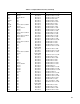
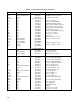
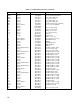
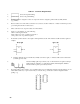
Component location illustrations (Figures 6-1 through 6-8), showing the physical location and reference designators of
almost all electrical parts. Components located on the A6 AC Input Board and on the output filter board mounted on
the output bus bars are easily identified by reference designators silkscreened on the boards.
b.
Notes (Table 6-1) that apply to all schematic diagrams.
c.
Schematic diagrams (Figures 6-9 through 6-13).
AC line voltage is present on the A1 Main Board Assembly whenever the power cord is connected to an ac
power source.