
Technical data
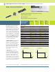


Agilent dc Electronic Loads maximize throughput with real-life loading conditions
Power Products Catalog 2002-2003
For more detailed specifications see the product manual at
www.agilent.com/find/power
76
Decrease system development time Lower cost of ownership
Increase system reliability Increase test system throughput
Increase system flexibility Stable operation down to zero volts
dc connection terminal for ATE applications
N3300A-N3307A
Multiple-Input: 150 W to 600 W
Control measurement speed vs. accuracy:
Decrease the number of measure-
ment samples to achieve greater
measurement speed, or increase the
number of samples to achieve higher
measurement accuracy. You can
optimize your measurements for
each test.
Control rising and falling slew rates
separately: Reduce rate of loading
change when necessary for DUT
stability or to simulate real life
conditions, but otherwise change
load values at maximum rate.
Increase System Flexibility…
for both present and
future requirements
Most power supply and battery
charger test systems designed today
need to test a variety of products
and/or assemblies. In the future,
additional products or assemblies
may be needed. A flexible family of
electronic loads makes present sys-
tem design and future growth much
easier.
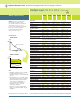
Test low voltage power supplies: The
N3300A series electronic loads oper-
ate with full stability down to zero
volts. Many other electronic loads
available today have been found to
become unstable in the operating
region below one volt. When design-
ing power supply test platforms,
the trend towards lower voltage
requirements should be taken into
account. Refer to the specification
and supplemental characteristic
tables for details of lower voltage
operating characteristics.
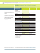
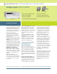
Choose dc load connection method:
Automatic test systems need
consistency and reliability. Option
UJ1 8 mm screw connectors provide
a simple screw onto which your
wires, terminated with insulated
ring terminals, may be securely
mounted. This optional connector
is specifically designed for test
systems. Wires may exit the plastic
cover in any direction, and multiple
wires may be placed on each screw
terminal for easy parallel load
connections. Up to AWG 4 wire
may be used.
Applications which require repeated
connections/disconections are better
suited to the standard connector.
The standard connector accepts
an unterminated wire, and may be
hand-tightened. This connector is
specifically designed for bench
applications and short-term auto-
mated tests.
Increase Test Throughput
Today’s high volume manufacturing
requires optimization of test system
throughput, to maximize production
volume without increasing floor-
space. The N3300A Series electronic
loads can help you in a number of
ways to achieve this goal.
Reduced command processing time:
Commands are processed more
than 10 times faster than previous
electronic loads.
Automatically execute stored command
sequences: “Lists” of downloaded
command sequences can execute
independent of the computer, greatly
reducing the electronic load command
processing time and computer inter-
action time during product testing.
Programmable delay allows for either
simultaneous or sequential load
changes: This is the most efficient
way to conduct testing of multiple
output dc power supplies, simulat-
ing real-life loading patterns, with a
minimum of programming com-
mands.
Buffer measurement data: Voltage,
current, and power measurements
can be buffered for later readback to
the computer, reducing computer
interaction.
Standard dc Option UJ1 8 mm
connectors screw connectors
3