
Technical data
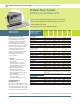


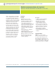

Overcome Battery Powered
Device Testing Challenges
Digital communications devices
and digital battery powered devices
present a unique testing challenge:
they draw rapid pulses of current.
By offering superior transient
performance, unmatched in the
marketplace, the Agilent Mobile
Communications dc Sources
dramatically reduce the transient
voltage drop due to pulse loading
characteristics of digital communi-
cations devices. The Agilent Mobile
Communications dc Sources enable
you to maximize test throughput by
minimizing test interruption due to
false trigger of device low voltage
shutdown.
Dynamic Measurement Capabilities
The Agilent Mobile Communications
dc Sources offer a built-in advanced
measurement system to accurately
measure battery current drains
when the device operates in differ-
ent modes (such as talk mode, active
mode, standby mode, and off/sleep
mode). Measurements made during
these modes are critical for ensuring
that your devices are operating
properly and that you are getting
the most out of the battery.
Simulate both Main Battery and Charger
Single output models are recom-
mended when you need to provide
power as a replacement to your
Agilent Application Specific dc Power Supplies tailored solutions for specific needs
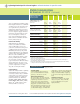
Specifications
(at 0
˚
to 55
˚
C unless
otherwise specified)
66309B/D 66311B/D 66319B/D 66321B/D 66332A 66332A-
J01
Special Order
Option
Power Products Catalog 2002-2003
For more detailed specifications see the product manual at
www.agilent.com/find/power
63
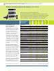
Ideal for testing wireless and battery powered devices
20 to 30 times improvement in test throughput over general purpose dc sources
Superior output transient performance with short or long load leads (up to 6 meters)
Dynamic measurement system for accurate battery current drain measurement
Easy-to-use Graphical User Interface and analysis tools for bench top use
Mobile Communications dc Sources: 40-100 W
Number of outputs 212111
GPIB Yes Yes Yes Yes Yes Yes
Output ratings
Voltage 0 to 15 V 0 to 15 V 0 to 15 V 0 to 15 V 0 to 20 V 0 to 30 V
Current 0 to 3 A 0 to 3 A 0 to 3 A 0 to 3 A 0 to 5 A 0 to 3.3 A
Peak current for up to 7 ms 5 A 5 A 5 A 5 A 5 A 3.3 A
Programming accuracy
at 25°C ±5°C (% of setting plus fixed)
Voltage 0.05%+ 10 mV 10 mV 10 mV 10 mV 10 mV 15 mV
+Current 0.05%+ 1.33 mA 1.33 mA 1.33 mA 1.33 mA 2 mA 2 mA
Ripple and Noise (20 Hz to 20 MHz)
Voltage rms 1 mV 1 mV 1 mV 1 mV 0.3 mV 0.5 mV
peak-to-peak 6 mV 6 mV 6 mV 6 mV 3 mV 5 mV
Current rms 2 mA 2 mA 2 mA 2 mA 2 mA 2 mA
dc measurement accuracy
Voltage 0.03%+ 5 mV 5 mV 5 mV 5 mV 3 mV 5 mV
+20 mA to + rated current 0.2%+ 0.5 mA
2
0.5 mA
2
— — 0.5 mA 0.5 mA
-20 mA to - rated current 0.2%+ 1.1 mA 1.1 mA — — 1.1 mA 1.1 mA
-3 A to + 5 A 0.2% — — 0.5 mA
2
0.5 mA
2
——
-1 A to + 1 A 0.1% — — 0.2 mA 0.2 mA — —
-20 mA to + 20 mA range 0.1%+ 2.5 µA 2.5 µA 2.5 µA 2.5 µA 2.5 µA 2.5 µA
Dynamic measurement system
Buffer size
4096 points 4096 points 4096 points 4096 points 4096 points 4096 points
Sampling interval 15 µs - 15 µs - 15 µs - 15 µs - 15 µs - 15 µs -
31,200 s 31,200 s 31,200 s 31,200 s 31,200 s 31,200 s
Transient response time <35 µs
3
<35 µs
3
<20 µs
3
<20 µs <100 µs
4
<100 µs
4
Transient voltage dip 70 mV 70 mV 40 mV 40 mV 500 mV 650 mV
(typical with up to 15 feet
22 AWG wiring)
Programmable output resistance
Range —- — -40 mΩ to -40 mΩ to — —
+1 Ω +1 Ω
Programming accuracy — — 0.5% + 0.5% + — —
2 mΩ 2 mΩ
Resolution — — 1 mΩ 1 mΩ ——
66319B/D, 66321B/D