
Technical data


116
Applications Information ac Power and Load Connections(Continued)
Power Products Catalog 2002-2003
For more detailed specifications see the product manual at
www.agilent.com/find/power
Agilent Technologies
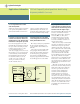
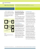
e. Load System Floated at a dc
Potential Above Ground.
It is sometimes necessary to operate
the power supply output at a fixed
voltage above or below ground
potential. The usual procedure in
these circumstances is to designate
a dc common point using whichever
of the preceding four alternatives is
appropriate, just as though conduc-
tive grounding were to be used.
Then connect this dc common point
to the dc ground point through a
1 microfarad capacitor as shown
in Figure 9.
Figure 9
Floating a Load System at a dc Potential
Above Ground
Select the dc Ground Point
STEP 6. Designate the terminal that
is connected to ground as the dc
ground point.
The dc ground point can be any
single terminal, existing or added,
that is conductively connected to the
ground of the building wiring system
and then eventually to earth ground.
STEP 7. Connect the dc common point
to the dc ground point, making certain
there is only one conductive path
between these two points.
Make this connection as shown in
Figures 4, 5, 6, or 7. Make the connec-
tion as short as possible and use a
wire size such that the total imped-
ance from the dc common point to
the dc ground point is not large
compared with the impedance from
the ground point to earth ground.
Flat braided leads are sometimes
used to further reduce the high
frequency component of the ground
lead impedance.
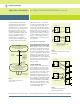
Making Remote Error Sensing
Connections
Normally a power supply operating
in the constant voltage mode
achieves its optimum line and load
regulation, its lowest output imped-
ance, drift, and PARD, and its fastest
transient recovery performance at
the power supply output terminals.
If the load is separated from the
output terminals by any lead length
(as in Fig. 10), some of these perfor-
mance characteristics will be
degraded at the load terminals-
usually by an amount proportional
to the impedance of the load leads
compared with the output imped-
ance of the power supply.
Figure 10
Load Voltage Variations Caused by Load Lead
Voltage Drops when Remote Error Sensing is
not Used
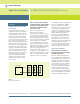
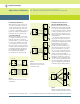
With remote error sensing, a feature
included in nearly all Agilent power
supplies, it is possible to connect the
input of the voltage feedback amplifi-
er directly to the load terminals
so that the regulator performs its
function with respect to the load
terminals rather than with respect to
the power supply output terminals.
Thus, the voltage at the power supply
output terminals shifts by whatever
amount is necessary to compensate
for the voltage drop in the load leads,
thereby maintaining the voltage at
the load terminals constant (Fig. 11).
Figure 11
Regulated Power Supply with Remote
Error Sensing.
Power Supply
+S
Load
GND
S.G.
CP
GP
1µf
-S
+
-
Power Supply
+S
R
L
-S
∆E
0
≠0
+
-
Power Supply
+ Sensing Lead
- Sensing Lead
+
R
L
-
∆E
0
≠0 ∆E
0
⯝0
+S
-S