
Technical data


115
Applications Information ac Power and Load Connections(Continued)
Power Products Catalog 2002-2003
For more detailed specifications see the product manual at
www.agilent.com/find/power
Agilent Technologies
b. Multiple Ungrounded Loads.
This alternative applies when sepa-
rate pairs of load leads connect two
or more loads and none of the load
circuits has an internal connection
to chassis or ground (Fig. 5). Use the
positive or negative dc distribution
terminal as the dc common point.
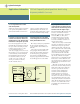
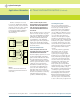
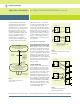
c. Single Grounded Load.
When a power supply is connected
to a single load that has a necessary
internal connection to chassis or
ground as in Fig. 6, or when a supply
is connected to multiple loads only
one of which has a necessary inter-
nal connection to chassis or ground
as in Fig. 7, the load terminals of the
grounded load must be designated
the dc distribution terminals, and
the grounded load terminal is
necessarily the dc common point.
Figure 6
Preferred Ground Connections for a Single
Grounded Load
Figure 7
Preferred Ground Connections for
Multiple Loads, Only One of Which
is Grounded Internally
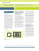
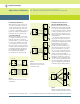
d. Multiple Loads, Two or More of
Which are Individually Grounded.
This undesirable situation must be
eliminated if at all possible. Ground
loop currents circulating through the
dc and load wiring cannot be avoided
so long as separate loads connected
to the same power supply or dc sys-
tem have separate ground returns as
shown in Fig. 8.
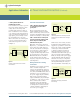
One possible solution is to break
the ground connection in all of the
loads and then select the dc common
point using the multiple ungrounded
load alternative as in (b) above.
Another would be to break the
ground connection in all but one of
the loads and select the dc common
point as in alternative (c). If there
are two or more loads with ground
connections that cannot be removed
and the system is susceptible to
ground loop problems, then the only
satisfactory solution is to increase
the number of power supplies and to
operate each grounded load from a
separate supply. Each combination
of power supply and grounded load
would be treated as in alternative (c).
Figure 8
Improperly Connected dc Distribution System
with Two Grounded Loads forming a Ground Loop
Power Supply
+S
Load
GND
S.G.
CP and GP
Without Remote Sensing
-S
+
-
Power Supply
+S
Load
GND
S.G.
CP and GP
With Remote Sensing
-S
+
-
With Remote Sensing
Power Supply
+S
Load
No 2
Load
No 1
Load
No 3
GND
S.G.
CP and GP
Without Remote Sensing
-S
+
-
Power Supply
+S
Load
No 2
Load
No 1
Load
No 3
GND
S.G.
CP and GP
-S
+
-
Power Supply
+S
Load
No 2
Load
No 1
Load
No 3
GND
S.G.
Ground
Voltage
Source
-S
+
-