
Technical data


114
Applications Information ac Power and Load Connections(Continued)
Power Products Catalog 2002-2003
For more detailed specifications see the product manual at
www.agilent.com/find/power
Agilent Technologies
to ground. With the instrument
panels fastened to the rack frame,
circulating ground currents are
inevitable. However, as long as these
ground currents are confined to the
ground system and do not flow
through any portion of the power
supply dc distribution wiring, their
effect on system performance is
usually negligible. To repeat,
separating the dc distribution
circuits from any conductive paths
in common with ground currents
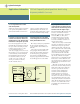
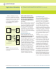
Figure 3
Isolating Ground Loop Paths from
the dc system
will in general reduce or eliminate
ground loop problems. The only way
to avoid such common paths is to
connect the dc distribution system to
ground with only one wire. Figure 3
illustrates this concept: dc and sig-
nal currents circulate within the dc
system, while ground loop currents
circulate within the ground system.
Steps, 5, 6, and 7 make specific rec-
ommendations for avoiding ground
loop problems.
Select the dc Common Point
STEP 5. Designate one of the dc distrib-
ution terminals as the dc common point.
There should be only one dc common
point in a dc system. If the supply is
to be used as a positive source, then
the negative dc distribution terminal
is the dc common point. If it is to be a
negative source, then the positive dc
distribution terminal is the dc com-
mon point. Here are some additional
suggestions for selecting the best
dc common point for five different
classes of loads:
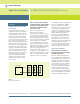
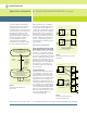
a. Single Isolated Load.
A single isolated load exists when a
power supply is connected to only
one load and the load circuit has no
internal connections to the chassis
or ground. If the power supply output
terminals are to be used as the dc
distribution terminals, then the dc
common point will be either the posi-
tive or negative power supply output
terminal (Fig. 4A). If remote sensing
is to be used and the load terminals
will serve as the distribution termi-
nals, then either the positive or nega-
tive load terminal will be the dc
common point (Fig. 4B).
Figure 4
Preferred Ground Connections for a Single
Isolated Load
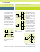
Figure 5
Preferred Ground Connections for
Multiple Ungrounded Loads
dc System
Ground System
dc Ground
Point (CP)
Consisting of all interconnected power supply
outputs, their dc distribution wiring and
associated load circuits.
Consisting of all chassis for power supplies
and their load devices, their ground
terminals, safety ground,
ac ground wiring, rack frames, etc.
dc Common
Point (CP)
dc ground
connection
All eventually lead
to earth ground
Only one wire
or connection
is permitted if
ground loop
currents are to
be kept out of
dc system
Power Supply
+S
Load
GND
S.G.
GP CP
A. Without Remote Sensing
S.G. = ”Safety Ground“ lead in power cord –
connected to chassis and ground terminals of
power supply, and to earth ground
GND = Power supply ground terminal
-S
+
-
Power Supply
+S
Load
GND
S.G.
GP CP
B. With Remote Sensing
-S
+
-
Without Remote Sensing
Power Supply
+S
Load
No. 1
Load
No. 2
-S
+
-
With Remote Sensing
CP
GP
S.G. GND
Power Supply
+S
Load
No. 1
Load
No. 2
-S
+
-
GP CP
S.G. GND