
Technical data


112
Applications Information ac Power and Load Connections(Continued)
Power Products Catalog 2002-2003
For more detailed specifications see the product manual at
www.agilent.com/find/power
Agilent Technologies
Load and Remote Error Sensing
Connections
Making Load Connections to One
Power Supply
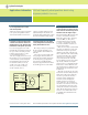
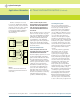
The simplest and most common
example of improper load wiring is
shown in Figure 1. The voltage at
each load depends on the current
drawn by the other loads and the
voltage drops they cause in some
portion of the load leads. Since most
load currents vary with time, an
interaction among the loads results.
This interaction can sometimes be
ignored, but in most applications the
resulting noise, pulse coupling, or
tendency toward inter-load oscilla-
tion is unacceptable. The following
thirteen steps describe a recom-
mended procedure for connecting
the load wiring, grounding the
system in a manner that avoids
troublesome ground loops, and
making connections for remote
error sensing.
Figure 1
Improper load connections
STEP 1. Select a load wire size that, as
an absolute minimum, is heavy enough to
carry the power supply output current
that would flow if the load terminals
were short-circuited.
This is the minimum, however.
Impedance and coupling
considerations usually dictate the
use of load wires larger than would
be required just to satisfy current
rating requirements. In general, the
power supply performance degrada-
tion seen at the load terminals
becomes significant when the wire
size and length result in a load wire
impedance comparable to or greater
than the effective output impedance
of the power supply. Refer to a
copper wire resistance table to see
if a larger wire size might have to be
used to attain an impedance compa-
rable to or smaller than the output
impedance of the power supply.
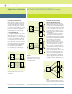
If multiple loads are supplied from
a pair of dc distribution terminals
not located at the power supply
terminals, it is necessary to consider
separately the mutual impedance
of the wires connecting the power
supply to the distribution terminals
and the additional impedance of
the wires to each individual load.
The mutual impedance presents an
opportunity for a variation of one
load current to cause a dc voltage
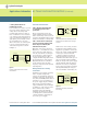
variation at another load. Fortunately
this mutual impedance can be
effectively reduced at dc and at low
frequencies by using remote error
sensing, as will be described later.
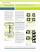
Connect the Load Wiring
STEP 2. Designate a single pair of
terminals as the positive and negative
dc distribution terminals.
These two terminals might be the
power supply output terminals, the
load terminals, or a separate pair of
terminals established expressly for
distribution. If the power supply is
a short distance from the load and
remote sensing will not be used,
locate the dc distribution terminals
as near as possible to the power
supply output terminals. Using the
power supply output terminals them-
selves as the distribution terminals
results in optimum performance.
Load
No1
Power Supply
+
-
Load
No2
Load
No3