
Technical data


109
Applications Information 10 Most frequently asked questions about using
dc power products
(Continued)
Power Products Catalog 2002-2003
For more detailed specifications see the product manual at
www.agilent.com/find/power
Agilent Technologies
7
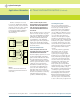
Can I use Agilent Electronic Loads in
series and in parallel?
Agilent electronic loads are designed
to be operated in parallel for more
current, but NOT in series for more
8
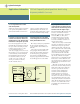
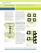
I must test a 1 volt power supply using a
constant current load and I want to use
Agilent Electronic Loads. But the Agilent
load meets all of its dynamic specs with
Use a boost supply in series with
the UUT. The load will now meet all
its specs with no derating, because
it always operates above 3 volts.
(see the illustration below)
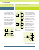
The boost supply can be a low-cost
fixed output 3 V or 5 V supply with
a current rating at least as high as
the maximum peak load current
needed. The 6641A (8 V, 20 A),
6651A (8 V, 50 A), 6671A (8 V,
220 A), or 6681A (8 V, 580 A)
are all excellent choices.
voltage. Loads are fully protected
against damage from current over-
loads, but will be damaged by voltage
above the maximum voltage rating.
no derating on down to 3 volts. Below
2 volts, the Agilent load current must be
linearly derated. What can I do?
The voltage setting of a programma-
ble boost supply should be set to
3 volts, and the current limit set to
full scale.
Select a boost power supply with
low p-p ripple and noise. The con-
stant current load will compensate
for low-frequency p-p ripple and
noise below a few kHz, but high
frequency ripple and noise from the
boost will appear across the UUT.
9
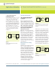
Why are Agilent’s Electronic Loads
constant resistance resolution speced in
ohms on the low resistance range, but in
mSiemens on the two higher ranges?
In general, Agilent’s Electronic Loads
are not a conventional “resistor”.
The loads consist of IC’s, capacitors,
resistors, FETs, etc. They were
designed with two major circuits,
a cv and cc circuit. These circuits
are used to simulate resistance on
the two upper ranges.
First, it is necessary to understand
why there is a difference in the way
in which the ranges are specified
(mohms or mS). The constant resis-
tance (CR) mode in the load actually
operates using either the constant
current (CC) or constant voltage
(CV) circuits inside the load. The
lowest CR range uses the CV regulat-
ing circuits, while the two higher
ranges use the CC regulating circuits.
It is because of these differences in
the circuits used to regulate the load
input that the specifications need to
be different.
When the CV circuits are used, the
load can be viewed as many resistors,
all the same value (the resolution),
in series to produce the desired
resistance. Then, changing the
resistance is like changing the
number of discrete resistors in
series. Therefore, the resolution is
the value of one of these series resis-
tors, and putting resistors in series
changes the resistance measured in
ohms. For the N3302A, the “discrete
resistor” or resolution that can be
programmed is 0.54 mohms in the
2 ohm range.
UUT
Boost
Supply
-
Out
- Sense
+ Sense
+ Out
+ Out
+ Sense
I
Load
Agilent
Load
+
Out
+ Sense
- Sense
- Out
- Sense
- Out