Agilent Power Products Catalog 2002-2003 Application Information and Technical Data for: dc Power Supplies dc Electronic Loads ac Power Solutions Application-Specific Power Solutions • Mobile Communications dc Sources • Solar Array Simulators • Component Test dc Source • Multi-Cell Charger/Discharger Power Products Modification Service Need Help with Power Products? www.agilent.
Agilent Technologies solutions to match your new test and measurement challenges. From Power Supplies to Power Solutions One quick browse through The cost and performance performance and reliability. Even benefits of the one-box approach our least-expensive dc supplies The central theme in all our power offer low ripple and noise with products is one-box integration– tight load and line regulation.
Agilent Technologies Table of Contents Selecting a System Power Supply Application Index Selection Index Feature Description Index 2-3 4 5-10 11-14 Basic dc Power Supplies…essential features for a tight budget 15 Single-Output: 30-60 W Multiple-Output: 35 and 50 W Triple-Output: 80 W GPIB Single-Output: 120-200 W GPIB Single & Dual Output: 30-100 W GPIB 16-17 18 19 20-21 22-23 Performance dc Power Supplies…speed and accuracy for test optimization 24 Single-Output: 40-50 W GPIB Single-Output: 80-100
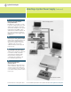
Agilent Technologies Selecting a System Power Supply 12 Factors to Consider when Selecting a System Power Supply 1 Does the power supply performance meet your requirements? Agilent 6600, 6800, and 66000 Series offer low output noise – among the best in their power ranges – allowing you to make even the most critical measurements. Active circuits ensure fast up and down programming, regardless of the load.
Agilent Technologies Selecting a System Power Supply (Continued) 9 How well is your load protected from potential failure? In addition to overvoltage, overcurrent and overtemperature protection, Agilent power supplies offer hardwired remote shutdown of the system independent of the GPIB. A userdefined fault condition anywhere in the system can trigger an alarm or shut down the power supply via the DFI/RI port.
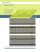
Agilent Technologies Application Index ar ra ys The models indicated for each application • • • • • • • • • • • • • • • • • • • • • • • • • • • • • • • • • • • • • • • • • • • • Power Products Catalog 2002-2003 • • • st te ns at ic un m o. N ge el M Pa od nt ile Ag N ss o.
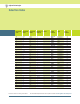
Agilent Technologies Selection Index Maximum Volts Maximum Amps Maximum Watts Number of Outputs GPIB Model Number Type Page Number 3.3 1000 3300 1 * 6680A-J04 Performance 48 48 5 875 4400 1 * 6680A Performance 5.7 20 100 up to 8 * 66101A-J03 Performance 60 6 2.5 15 3 E3630A Basic 18 6 5 30 3 E3631A Basic 19 6 60 360 1 6551A-J03 Performance 37 6 60 360 1 6651A-J03 Performance 34 6.7 30 200 1 * 6033A Autoranging 53 7 0.015 0.
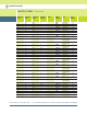
Agilent Technologies Selection Index (Continued) Maximum Volts Maximum Amps Maximum Watts Number of Outputs GPIB Model Number Type 8 220 1760 1 * 6671A Performance 39 8 580 4600 1 * 6681A Performance 48 10 5 50 1 * 6611C-J05 Performance 25 10 50 500 1 6551A-J01 Performance 37 10 50 500 1 6651A-J01 Performance 33 10 200 2000 1 6571A-J04 Performance 46 10 200 2000 1 * 6671A-J04 Performance 40 +/-10.25 +/-0.5125 5.
Agilent Technologies Selection Index (Continued) Maximum Volts Maximum Amps Maximum Watts Number of Outputs GPIB Model Number Type 16 0.2 3.2 17 30 510 20 0.5 10 3 20 1.5 30 1 20 1.5 30 1 * 20 1.
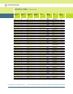
Agilent Technologies Selection Index (Continued) Maximum Volts Maximum Amps Maximum Watts Number of Outputs GPIB Model Number Type 28 5 140 up to 8 * 66103A-J09 Performance 61 30 3.3 100 1 * 66332A-J01 Mobile Communications 63 30 4 120 1 * E3632A Basic 20 30 17.5 500 1 * 6653A-J17 Performance 34 30 17.5 525 1 6553A-J17 Performance 37 30 220 6600 1 * 6691A Performance 50 32 160 5100 1 * 6683A Performance 48 35 0.
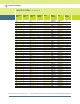
Agilent Technologies Selection Index (Continued) Maximum Volts Maximum Amps Maximum Watts Number of Outputs GPIB Model Number Type 50 1 50 4 * 6626A Performance 57 50 1 50 2 * 6628A Performance 57 50 1 50 4 * 6629A Performance 57 50 2 80 2 * 6622A Performance 55 50 2 100 1 * 6633B Performance 27 50 4 200 1 * E3634A Basic 20 50 4 200 1 E3634A Basic 20 50 10 500 1 6554A-J05 Performance 38 50 10 500 1 6654A-J05 Performance 35 50 42
Agilent Technologies Selection Index (Continued) Maximum Volts Maximum Amps Maximum Watts Number of Outputs 70 7.5 500 1 70 7.5 500 1 80 6 480 1 80 6 500 1 86 6 516 100 0.5 100 1 100 22 2000 1 100 22 2000 1 110 20 2000 1 110 20 2000 1 120 0.25 30 1 120 1.25 150 up to 8 120 1.5 180 1 120 1.5 180 1 120 4.5 540 1 120 4 540 1 120 18 2160 1 120 18 2160 1 130 4 480 1 135 16 2000 1 135 16 2000 1 150 1.2 150 1 150 1.
Agilent Technologies Ou 2000 W - 1200 W 6600 W 40 W100 W 30 W 200 W 50 V 120 V 120 V 200 V 20 V 60 V 10 V 2A 50 A 875 A 16 A 5A 20 A 0.5 A 57 29, 33 39, 48, 50 59 63 18, 22 71 5W Configuration Features • “One-box” solution To preserve rack space and interconnections, the voltage and current programmers, current shunt, and DVM are built-in to one package.
Ou Single Range + Peak Current Pulse A limited amplitude and limited width v current pulse can be sourced beyond the maximum static current limit. Autoranging A wide, continuous range of voltage and v current combinations are available automatically at the maximum power level. Multiple-output range changing Automatic range changing gives maximum power to v two different voltage and current combinations.
Ou GPIB Programming Features • • • • • • • • • • Measured voltage and current read-back over the GPIB The output is read back in units of volts and amps. • • • • • • • • • • 0 4 0 4 5 6670-5 6680-4 6690-4 5 4 5 0 16/5 0 10 7 0 0 5 0 0 0 • • • • • • • • GPIB programmable overvoltage protection Can be enabled to quickly down-program the output and set SRQ and/or DFI/RI. T = Can generate trigger.
10 V 20 A 0.5 A 39, 48, 50 59 63 18, 22 71 40 W & 80 W 25 W & 50 W 200 W 500 W Max Voltage 500 V 100 V 50 V 50 V Max Current 120 A 10 A 10 A 2A Page 53 25, 27 55 57 29, 33 Ou • • O O • • • • SRQ Almost any fault condition or change of state of the power supply can be enabled to generate an SRQ. This signals the computer to take the appropriate action. • • • • • • • • Local lockout Front-panel or keyboard control can be disabled.
Agilent Technologies Basic dc Power Supplies...essential features for a tight budget Performance dc Power Supplies...speed and accuracy for test optimization Application Specific dc Power Supplies...Tailored solutions for specific needs dc Electronic Loads...maximize throughput with real life loading conditions ac Power Source/Analyzers...an integrated ac power solution Basic dc Power Supplies Agilent Basic dc Power Supplies are the right choice for many applications.
Agilent Basic dc Power Supplies essential features for a tight budget Single-Output: 30-60 W E3610A-E3617A Convenient size for bench use Low noise and excellent regulation Easy to use Specifications E3610A E3611A E3612A E3614A Number of output ranges 2 2 2 1 GPIB No No No No Range 1 0 to 8 V, 0 to 3 A1 0 to 20 V, 0 to 1.5 A1 0 to 60 V, 0 to 0.5 A1 0 to 8 V, 0 to 6 A Range 2 0 to 15 V, 0 to 2 A1 0 to 35 V, 0 to 0.85 A1 0 to 120 V, 0 to 0.
Agilent Basic dc Power Supplies essential features for a tight budget Single-Output: 30-60 W (Continued) Specifications E3615A E3616A E3617A Number of output ranges 1 1 1 GPIB No No No (at 0 ˚ to 55˚ C unless otherwise specified) Supplemental Characteristics for all model numbers Output ratings1 Range 1 0 to 20 V, 0 to 3 A 0 to 35 V, 0 to 1.7 A 0 to 60 V, 0 to 1 A Size: E3610A-E3612A: 91 mm H x 213 mm W x 319 mm D (3.6 in x 8.4 in x 12.
Agilent Basic dc Power Supplies essential features for a tight budget Multiple-Output: 35 W and 50 W E3620A, E3630A Convenient size for bench use Low noise and excellent regulation Easy to use Specifications E3620A E3630A Number of Outputs 2 3 GPIB No No Output 1 0 to 25 V, 0 to 1 A 0 to 6 V, 0 to 2.5 A* Output 2 0 to 25 V, 0 to 1 A 0 to +20 V, 0 to 0.5 A Output 3 — 0 to -20 V, 0 to 0.
Agilent Basic dc Power Supplies essential features for a tight budget Triple-Output: 80 W GPIB E3631A Convenient size for the R&D bench Triple output GPIB and RS232 for automated testing Specifications E3631A (at 0 ˚ to 55 ˚ C unless otherwise specified) This is the dc power supply for every engineer’s or electronic technician’s lab bench. It has two tracking 25 V outputs, which are together referenced to a floating common, and an isolated 6 volt output.
Agilent Basic dc Power Supplies essential features for a tight budget Single-Output: 120 W to 200 W GPIB E3632A-E3634A Convenient size for the R&D bench Flexibility of dual range GPIB and RS232 to easily automate tests Accurate programming and measurement Specifications E3632A E3633A E3634A (at 0 ˚ to 55 ˚ C unless otherwise specified) These dual range dc power supplies provide the stable, accurate, and reliable dc power that the R&D engineer needs.
Agilent Basic dc Power Supplies essential features for a tight budget Single-Output: 120 W to 200 W (Continued) Supplemental Characteristics for all model numbers Product Regulation: Designed to comply with UL1244, IEC 61010-1; certified with CSA 22.2 Meets requirements for CE regulation Warranty: Three years Size: 213 mm W x 132 mm H x 348 mm D (8.4 in. x 5.2 in. x 13.7 in.) Weight: 9.
Agilent Basic dc Power Supplies essential features for a tight budget Single & Dual Output: 30-100 W GPIB E3640A-E3645A E3646A-E3649A Convenient system wiring with front and rear panel terminals Flexibility of dual range Single or dual output Easy system interface with GPIB and RS232 Specifications E3640A E3641A E3642A E3643A E3644A (at 0 ˚ to 55 ˚ C unless otherwise specified) These isolated dual range dc power supplies provide the stable and reliable dc power that the manufacturing test system
Agilent Basic dc Power Supplies essential features for a tight budget Single & Dual Output: 30-100 W GPIB (Continued) Specifications E3645A E3646A E3647A E3648A E3649A (at 0 ˚ to 55˚ C unless otherwise specified) Number of outputs 1 2 2 2 2 GPIB Yes Yes Yes Yes Yes Supplemental Characteristics for all model numbers dc outputs dc Floating Voltage: Output terminals can be floated up to ±240 Vdc from chassis ground Voltage Current 0 to 35 V 2.2 A 0 to 8 V 3A 0 to 35 V 0.
Agilent Technologies Basic dc Power Supplies...essential features for a tight budget Performance dc Power Supplies...speed and accuracy for test optimization Application Specific dc Power Supplies...Tailored solutions for specific needs dc Electronic Loads...maximize throughput with real life loading conditions ac Power Source/Analyzers...
Agilent Performance dc Power Supplies speed and accuracy for test optimization Single-Output: 40-50 W GPIB 6611C - 6614C Increase production throughput with fast programming speed and fast downprogramming time Protect valuable prototypes with fast protection features Accurate and fast built-in measurement system Specifications 6611C 6612C 6613C 6614C (at 0 ˚ to 55 ˚ C unless otherwise specified) This series of linear-regulated 40-50 W dc power supplies is designed to maximize the throughput of DUTs
Agilent Performance dc Power Supplies speed and accuracy for test optimization Single-Output: 40-50 W GPIB (Continued) Supplemental Characteristics for all model numbers dc Floating Voltage: Output terminals can be floated up to ±240 Vdc maximum from chassis ground Remote Sensing: Up to two volts dropped in each load lead. Add 2 mV to the voltage load regulation specification for each one volt change in the postive output lead due to load current change.
Agilent Performance dc Power Supplies speed and accuracy for test optimization Single-Output: 80-100 W GPIB 6631B - 6634B Increase production throughput with fast programming speed Active downprogrammer sinks the full rated current Protect valuable prototypes with fast protection features Accurate and fast built-in measurement system Specifications 6631B 6632B 6633B 6634B Number of outputs 1 1 1 1 GPIB Yes Yes Yes Yes (at 0 ˚ to 55 ˚ C unless otherwise specified) This series of linear-reg
Agilent Performance dc Power Supplies speed and accuracy for test optimization Single-Output: 80-100 W GPIB (Continued) Specifications 6631B 6632B 6633B 6634B (at 0 ˚ to 55˚ C unless otherwise specified) Supplemental Characteristics Supplemental Characteristics for all model numbers (Non-warranted characteristics determined by design and useful in applying the product) Average programming resolution Voltage 2 mV 5 mV 12.
Agilent Performance dc Power Supplies speed and accuracy for test optimization Single-Output: 200 W GPIB 6641A - 6645A Increase test throughput with fast up and down programming time Protect valuable assemblies with fast protection features Proven reliability Low ripple and noise Specifications 6641A 6642A 6643A 6644A 6645A (at 0 ˚ to 55 ˚ C unless otherwise specified) This series of 200 W linear-regulated dc power supplies is designed to maximize the throughput of DUTs through the manufacturing t
Agilent Performance dc Power Supplies speed and accuracy for test optimization Single-Output: 200 W GPIB (Continued) Specifications (at 0 ˚ to 55˚ C unless otherwise specified) Supplemental Characteristics for all model numbers dc Floating Voltage: Output terminals can be floated up to ±240 Vdc from chassis ground Remote Sensing: Up to half the rated output voltage can be dropped in each load lead. The drop in the load leads subtracts from the voltage available for the load.
Agilent Performance dc Power Supplies speed and accuracy for test optimization Single-Output: 200 W 6541A-6545A Protect valuable assemblies with fast protection features Proven reliability Low ripple and noise Specifications 6541A 6542A 6543A 6544A 6545A Number of outputs 1 1 1 1 1 GPIB No No No No No (at 0 ˚ to 55˚ C unless otherwise specified) This reliable series of 200 W dc power supplies can be controlled either from the front panel or via an analog programming voltage.
Agilent Performance dc Power Supplies speed and accuracy for test optimization Single-Output: 200 W (Continued) Specifications 6541AJ04 6544AJ09 6545AJ05 Special Order Option Special Order Option Special Order Option Number of outputs 1 1 1 GPIB No No No (at 0 ˚ to 55˚ C unless otherwise specified) Supplemental Characteristics for all model numbers Output ratings Output voltage 13 V 70 V 150 V dc Floating Voltage: Output terminals can be floated up to ±240 Vdc from chassis ground Outp
Agilent Performance dc Power Supplies speed and accuracy for test optimization Single-Output: 500 W GPIB 6651A-6655A Increase test throughput with fast up and down programming time Protect valuable assemblies with fast protection features Proven reliability Low ripple and noise Specifications 6651A 6652A 6653A 6654A 6655A (at 0 ˚ to 55 ˚ C unless otherwise specified) This series of 500 W linear-regulated dc power supplies is designed to maximize the throughput of DUTs through the manufacturing tes
Agilent Performance dc Power Supplies speed and accuracy for test optimization Single-Output: 500 W GPIB (Continued) Specifications (at 0 ˚ to 55˚ C unless otherwise specified) Supplemental Characteristics for all model numbers Remote Sensing: Up to half the rated output voltage can be dropped in each load lead. The drop in the load leads subtracts from the voltage available for the load.
Agilent Performance dc Power Supplies speed and accuracy for test optimization Single-Output: 500 W GPIB (Continued) Specifications 6654AJ04 6654AJ05 6654AJ12 6655AJ05 6655AJ10 Special Order Option Special Order Option Special Order Option Special Order Option Special Order Option Number of outputs 1 1 1 1 1 GPIB Yes Yes Yes Yes Yes Output voltage 70 V 50 V 80 V 150 V 156 V Output current (40˚C) 7.5 A 10 A 6A 3.2 A 3A Maximum current (50˚C/55˚C) 6.75 A/6.37 A 9 A/8.
Agilent Performance dc Power Supplies speed and accuracy for test optimization Single-Output: 500 W 6551A-6555A Protect valuable assemblies with fast protection features Proven reliability Low ripple and noise Specifications 6551A 6552A 6553A 6554A 6555A Number of outputs 1 1 1 1 1 GPIB No No No No No (at 0 ˚ to 55 ˚ C unless otherwise specified) This reliable series of 500 W dc power supplies can be controlled either from the front panel or via an analog programming voltage.
Agilent Performance dc Power Supplies speed and accuracy for test optimization Single-Output: 500 W (Continued) Specifications 6551A-J01 6551A-J03 6553A-J04 6553A-J17 Special Order Option Special Order Option Special Order Option Special Order Option Number of outputs 1 1 1 1 GPIB No No No No Output voltage 10 V 6V 40 V 30 V Output current (40° C) 50 A 60 A 12.5 A 17.5 A Maximum current (50° C/55° C) 45 A/42.5 A 54 A/51 A 11.25 A/10.6 A 15.75 A/14.
Agilent Performance dc Power Supplies speed and accuracy for test optimization Single-Output: 500 W (Continued) Specifications 6554A-J04 6554A-J05 6554A-J12 6555A-J10 Special Order Option Special Order Option Special Order Option Special Order Option Number of outputs 1 1 1 1 GPIB No No No No Output voltage 70 V 50 V 80 V 156 V Output current (40° C) 7.5 A 10 A 6A 3A Maximum current (50° C/55° C) 6.75 A/6.37 A 9 A/8.5 A 5.4 A/5.1 A 2.7 A/2.
Agilent Performance dc Power Supplies speed and accuracy for test optimization Single-Output: 2000 W GPIB 6671A - 6675A Proven reliability Increase test throughput with fast up and down programming High efficiency Low ripple and noise Specifications 6671A 6672A 6673A 6674A 6675A Number of outputs 1 1 1 1 1 GPIB Yes Yes Yes Yes Yes Output voltage 0 to 8 V 0 to 20 V 0 to 35 V 0 to 60 V 0 to 120 V Output current 0 to 220 A 0 to 100 A 0 to 60 A 0 to 35 A 0 to 18 A 8 mV 20 mV 3
Agilent Performance dc Power Supplies speed and accuracy for test optimization Single-Output: 2000 W GPIB (Continued) Specifications (at 0 ˚ to 55˚ C unless otherwise specified) Supplemental Characteristics for all model numbers 6671AJ03 6671AJ04 6671AJ17 6672AJ04 6673AJ03 Special Order Option Special Order Option Special Order Option Special Order Option Special Order Option Number of outputs 1 1 1 1 1 GPIB Yes Yes Yes Yes Yes Output ratings Output voltage 14 V 10 V 15 V 24 V
Agilent Performance dc Power Supplies speed and accuracy for test optimization Single-Output: 2000 W GPIB (Continued) Specifications 6673AJ08 6674AJ03 6674AJ07 6675AJ04 6675AJ06 Special Order Option Special Order Option Special Order Option Special Order Option Special Order Option Number of outputs 1 1 1 1 1 GPIB Yes Yes Yes Yes Yes Output voltage 40 V 56 V 50 V 160 V 135 V Output current 50 A 38 A 42 A 13 A 16 A (at 0 ˚ to 55 ˚ C unless otherwise specified) Ordering In
Agilent Performance dc Power Supplies speed and accuracy for test optimization Single-Output: 2000 W GPIB (Continued) Specifications 6675AJ07 6675AJ08 6675AJ09 6675A J11 Special Order Option Special Order Option Special Order Option Special Order Option Number of outputs 1 1 1 1 GPIB Yes Yes Yes Yes Output voltage 200 V 100 V 110 V 150 V Output current 11 A 22 A 20 A 15 A 200 mV 120 mV 120 mV 150 mV 8 mA 15 mA 13.5 mA 11 mA Voltage rms 3.5 mV 1.9 mV 1.9 mV 2.
Agilent Performance dc Power Supplies speed and accuracy for test optimization Single-Output: 2000 W GPIB E4356A Flexibility of Dual Range Increase test throughput with fast up and down programming High efficiency Low ripple and noise Specifications E4356A (at 0 ˚ to 55 ˚ C unless otherwise specified) This 2000 W dc power supply provides over 2000 watts at either 70 or 80 volts. This makes it particularly suitable for a variety of test scenarios for 48 volt systems.
Agilent Performance dc Power Supplies speed and accuracy for test optimization Single-Output: 2000 W GPIB (Continued) Supplemental Characteristics for all model numbers dc Floating Voltage: Output terminals can be floated up to ±240 Vdc maximum from chassis ground. Remote Sensing: Up to half the rated output voltage can be dropped in each load lead. The drop in the load leads subtracts from the voltage available for the load.
Agilent Performance dc Power Supplies speed and accuracy for test optimization Single-Output: 2000 W 6571A-6575A Proven reliability High efficiency Low ripple and noise Specifications 6571A 6572A 6573A 6574A 6575A (at 0 ˚ to 55 ˚ C unless otherwise specified) This series of 2000 watt dc power supplies has the exceptional, proven reliability that test system engineers look for. It also has the unusual combination of high efficiency and low noise operation.
Agilent Performance dc Power Supplies speed and accuracy for test optimization Single-Output: 2000 W (Continued) Specifications (at 0 ˚ to 55˚ C unless otherwise specified) Supplemental Characteristics for all model numbers dc Floating Voltage: Output terminals can be floated up to ±240 Vdc from chassis ground Output Common-Mode Noise Current: (to signal ground binding post) 500 µ A rms, 4 mA peak-to-peak Remote Sensing: Up to half the rated output voltage can be dropped in each load lead.
Agilent Performance dc Power Supplies speed and accuracy for test optimization Single-Output: 2000 W (Continued) Specifications (at 0 ˚ to 55 ˚ C unless otherwise specified) Ordering Information Opt 200 174 to 220 Vac, 47 to 63 Hz (Japan only) Opt 230 191 to 250 Vac, 47 to 63 Hz * Opt 908 Rack-mount Kit (p/n 5062-3977) * Opt 909 Rack-mount Kit w/ Handles (p/n 5063-9221) Opt 0L2 Extra Standard Documentation Package Opt 0B3 Service Manual Opt 0B0 No documentation package A line cord option must be specified
Agilent Performance dc Power Supplies speed and accuracy for test optimization Single-Output: 5000 W GPIB Proven reliabilty Increase test throughput 6680A-6684A with fast up and down programming Fast reaction to analog programming signals Specifications 6680A 6681A 6682A 6683A 6684A (at 0 ˚ to 55 ˚ C unless otherwise specified) Reliable dc power for manufacturing test and long-term burn-in This series of 5000 watt dc power supplies has the exceptional, proven reliability that test system enginee
Agilent Performance dc Power Supplies speed and accuracy for test optimization Single-Output: 5000 W GPIB (Continued) Supplemental Characteristics for all model numbers dc Floating Voltage: Output terminals can be floated up to ±60 Vdc maximum from chassis ground Remote Sensing: Up to half the rated output voltage can be dropped in each load lead. The drop in the load leads subtracts from the voltage available for the load.
Agilent Performance dc Power Supplies speed and accuracy for test optimization Single-Output: 6600 W GPIB Proven reliabilty 6690A-6692A Increase test throughput with fast up and down programming Fast reaction to analog programming signals Specifications 6690A 6691A 6692A (at 0 ˚ to 55 ˚ C unless otherwise specified) Reliable dc power for manufacturing test and long-term burn-in This series of 6600 watt dc power supplies has the exceptional, proven reliability that test system engineers look for.
Agilent Performance dc Power Supplies speed and accuracy for test optimization Single-Output: 6600 W GPIB (Continued) Specifications 6690A 6691A 6692A (at 0 ˚ to 55 ˚ C unless otherwise specified) Supplemental Characteristics Supplemental Characteristics for all model numbers Ripple and noise constant current mode from 20 Hz to 20 MHz rms dc Floating Voltage: Output terminal can be floated up to ±60 Vdc from chassis ground Remote Sensing: Up to half the rated output voltage can be dropped in each l
Agilent Performance dc Power Supplies speed and accuracy for test optimization Single-Output, Autoranging: 200 W and 1000 W 6010A, 6011A, 6012B, 6015A Autoranging Output: V1 Volts Save rack space by using fewer outputs P1 Reduce cost by using fewer power supplies P2 V2 V3 P3 I1 I2 Control with external voltage I3 Amps Specifications 6010A 6011A 6012B 6015A Number of outputs 1 1 1 1 GPIB No No No No Voltage 0 to 200 V 0 to 20 V 0 to 60 V 0 to 500 V Current 0 to 17 A 0 to 120
Agilent Performance dc Power Supplies speed and accuracy for test optimization 6033A, 6038A Single-Output, Autoranging: 200 W and 1000 W GPIB Autoranging Output: V1 Volts Save rack space by using fewer outputs Reduce cost by using fewer power supplies P1 P2 V2 V3 6030A, 6031A, 6032A, 6035A P3 I1 I2 I3 Amps Specifications 6030A 6031A 6032A 6033A 6035A 6038A Number of outputs 1 1 1 1 1 1 GPIB Yes Yes Yes Yes Yes Yes Output Voltage 0 to 200 V 0 to 20 V 0 to 60 V 0 to 20 V 0
Agilent Performance dc Power Supplies speed and accuracy for test optimization Autoranging: 200 W and 1000 W GPIB (Continued) Specifications 6030A 6031A 6032A 6033A 6035A 6038A (at 0˚ to 55 ˚ C unless otherwise specified) Supplemental Characteristics for all model numbers Supplemental Characteristics (Non-warranted characteristics determined by design and useful in applying the product) Programming resolution Voltage 50 mV 5 mV 15 mV 5 mV 125 mV 1 5 mV 4.25 mA 30 mA 12.5 mA 7.5 mA 1.
Agilent Performance dc Power Supplies speed and accuracy for test optimization Multiple-Output: 40 W-105 W GPIB 6621A-6624A, 6627A Fast up and down programming Proven reliability keeps test systems running Easy to integrate into a system Extensive protection for DUTs Specifications 40 W output 40 W output 80 W 80 W output output 105 W output Low-range volts, amps 0 to 7 V, 0 to 5 A 0 to 20 V, 0 to 2 A 0 to 7 V, 0 to 10 A 0 to 20 V, 0 to 4 A 0-35 V, 0-3 A High range volts, amps 0 to 20 V, 0 to
Agilent Performance dc Power Supplies speed and accuracy for test optimization Multiple-Output: 40 W-105 W GPIB (Continued) Specifications 40 W output (at 0 ˚ to 55˚ C unless otherwise specified) Supplemental Characteristics Supplemental Characteristics for all model numbers dc Floating Voltage: All outputs can be floated up to ±240 Vdc from chassis ground Remote Sensing: Up to 1 V drop per load lead. The drop in the load leads is subtracted from the voltage available for the load.
Agilent Performance dc Power Supplies speed and accuracy for test optimization Precision Multiple-Output: 25 W-50 W GPIB 6625A, 6626A, 6628A, 6629A Precise V & I programming and readback Fast up and down programming Extensive protection for DUTs Easy to integrate into a system Specifications 25 W output 50 W output (at 0 ˚ to 55 ˚ C unless otherwise specified) Two or four isolated outputs are integrated into one package, conserving rack space and GPIB addresses.
Agilent Performance dc Power Supplies speed and accuracy for test optimization Precision Multiple-Output: 25 W-50 W GPIB (Continued) Supplemental Characteristics for all model numbers dc Floating Voltage: All outputs can be floated up to ±240 Vdc from chassis ground Remote Sensing: Up to 10 V drop per load lead. The drop in the load leads is subtracted from the voltage available for the load. Command Processing Time: 7 ms typical with front-panel display disabled Input Power: 550 W max., 720 VA max.
Agilent Performance dc Power Supplies speed and accuracy for test optimization Modular Power System: 1200 W per mainframe GPIB Save rack space with 8 power supply outputs in one mainframe Increase test throughput with advanced triggering system and down-loadable LIST mode Reconfigure fast with easily swappable modules 66000A (mainframe) 66001A (keyboard) 66000 Modular Power System The Agilent 66000 modular power system simplifies test-system assembly, cabling, programming, debugging and operation.
Agilent Performance dc Power Supplies speed and accuracy for test optimization Modular Power System: 1200 W per mainframe GPIB (Continued) Specifications 66101AJ03 66101AJ05 66102A- 66103AJ05 J01 66103AJ02 Special Order Option Special Order Option Special Order Option Special Order Option Special Order Option Output voltage 5.7 V 12 V 15 V 37 V 40 V Output current 20 A 12 A 10 A 4.5 A 3.
Agilent Performance dc Power Supplies speed and accuracy for test optimization Modular Power System: 1200 W per mainframe GPIB (Continued) Specifications 66103AJ09 66103AJ12 66104AJ09 66105AJ01 Special Order Option Special Order Option Special Order Option Special Order Option Output voltage 28.5 V 24 V 55 V 35 V Output current 5.5 A 6A 3A 1.
Agilent Technologies Basic dc Power Supplies...essential features for a tight budget Performance dc Power Supplies...speed and accuracy for test optimization Application Specific dc Power Supplies...Tailored solutions for specific needs dc Electronic Loads...maximize throughput with real life loading conditions ac Power Source/Analyzers...an integrated ac power solution Application Specific dc Power Supplies Mobile Communication dc Sources Some applications require specialized dc power supplies.
Agilent Application Specific dc Power Supplies tailored solutions for specific needs Mobile Communications dc Sources: 40-100 W Ideal for testing wireless and battery powered devices 20 to 30 times improvement in test throughput over general purpose dc sources Superior output transient performance with short or long load leads (up to 6 meters) Dynamic measurement system for accurate battery current drain measurement Easy-to-use Graphical User Interface and analysis tools for bench top use 66319B/D, 66321B/
Agilent Application Specific dc Power Supplies tailored solutions for specific needs Mobile Communications dc Sources: 40-100 W (Continued) Specifications 66309B/D 66311B/D 66319B/D 66321B/D 66332A (at 0 ˚ to 55˚ C unless otherwise specified) device’s main battery during testing.
Agilent Application Specific dc Power Supplies tailored solutions for specific needs Mobile Communications dc Sources: 40-100 W (Continued) Supplemental Characteristics (Non-warranted characteristics determined by design and useful All models offer: • Fast output response technology • Programmable output response compensation • Advanced DSP-based dynamic measurements • Current sinking for testing and calibrating charger circuitry • Extensive protection features (including broken sense lead detection) • G
Agilent Application Specific dc Power Supplies tailored solutions for specific needs Mobile Communications dc Sources: 40-100 W (Continued) Ordering Information Opt 100 87 to 106 Vac, 47 to 63 Hz Opt 120 104 to 127 Vac, 47 to 63 Hz Opt 220 191 to 233 Vac, 47 to 63 Hz Opt 230 207 to 253 Vac, 47 to 63 Hz Opt 004 Make “Hi Compensation Mode” as default setting Opt 020 Front-panel Binding Posts (66332A only) Opt UJ0 No front panel binding posts (66332A only) Opt 053 Add 14565A Device Characterization Software
Agilent Application Specific dc Power Supplies tailored solutions for specific needs Mobile Communications dc Sources: Device Characterization Software Ideal for testing wireless and battery powered devices Converts Mobile Communications dc Source into a powerful bench top tool for R&D and Repair Easy-to-use Graphical User Interface and analysis tools No programming required Simplify test and analysis in R&D or on the repair bench With the Agilent 14565A Device Characterization Software, testing, analyzin
Agilent Application Specific dc Power Supplies tailored solutions for specific needs Mobile Communications dc Sources: Device Characterization Software (Continued) When coupled with the 66319B/D or the 66321B/D, the 14565A also provides Battery Drain Analysis capabilities. More than just measuring battery run time, Battery Drain Analysis allows you to characterize current out of the battery and make tradeoffs in design that impact the current drain and battery life.
Agilent Application Specific dc Power Supplies tailored solutions for specific needs Solar Array Simulators E4350B, E4351B Fast and accurate simulation of any type of solar array Multiple simulation modes Fast recovery time Easy to simulate environmental conditions Specifications E4350B E4351B (at 0 ˚ to 55 ˚ C unless otherwise specified) The Agilent one-box Solar Array Simulator (SAS) is a dc power source that simulates the output characteristics of a solar array.
Agilent Application Specific dc Power Supplies tailored solutions for specific needs Solar Array Simulators (Continued) Specifications E4350BJ03 E4350BJ04 E4350BJ06 Special Order Option Special Order Option Special Order Option Number of outputs 1 1 1 GPIB Yes Yes Yes Max. Power 480 W 480 W 480 W Voc. Max. 52 V 47 V 74 V Isc. Max. 10 A 11 A 7A (at 0 ˚ to 55˚ C unless otherwise specified) Non-volatile memory can store a maximum of 3500 points.
Agilent Application Specific dc Power Supplies tailored solutions for specific needs N3280A Component Test dc Source 3 N3280A Save valuable rack space with 4 outputs in a one-half rack box Increase system throughput with fast command processing time Accurately measure low level (nA) currents with its 16-bit measurement system Synchronize measurements to an external event using the trigger system Specifications Voltage Priority Mode Current Priority Mode Applies to each of the four identical outputs
Agilent Application Specific dc Power Supplies tailored solutions for specific needs N3280A Component Test dc Source (Continued) Specifications Voltage Priority Mode Current Priority Mode Voltage ±200 µV N/A +Current limit ±10 µA N/A -Current limit ±10 µA N/A Current N/A ±10 nA Applies to each of the four identical outputs (at 25 ˚ ± 5˚ C) measurement ranges allows you to accurately measure low-level (nA) currents. This quad–output source is easy to integrate into a test system.
Agilent Application Specific dc Power Supplies tailored solutions for specific needs N3280A Component Test dc Source (Continued) Ordering Information Supplemental Characteristics for all model numbers dc Floating Voltage: Output terminals can be floated up to ±50 Vdc maximum from chassis ground and ±100 Vdc from output to output. Remote Sensing: Up to 1/2 the maximum output voltage may be dropped across each load lead. Add 1/2 mV to the load regulation for each 1 V change in the HI output lead.
Agilent Application Specific dc Power Supplies tailored solutions for specific needs Agilent Application-Specific dc Power Supplies: Multi-Cell Charger/Discharger (MCCD) Easy system integration Integrated safety and protection features E4370A Accurate measurements Grouping capability Fully programmable Condition Value for E4370A with E4374A Value for E4370A with E4375A Maximum programmable output voltage charging 5V 5V Maximum compliance voltage (cell voltage + fixture/wiring voltage drops) charg
Agilent Technologies Basic dc Power Supplies...essential features for a tight budget Performance dc Power Supplies...speed and accuracy for test optimization Application Specific dc Power Supplies...Tailored solutions for specific needs dc Electronic Loads...maximize throughput with real life loading conditions ac Power Source/Analyzers...
Agilent dc Electronic Loads maximize throughput with real-life loading conditions Multiple-Input: 150 W to 600 W 3 Standard dc connectors N3300A-N3307A Option UJ1 8 mm screw connectors Decrease system development time Lower cost of ownership Increase system reliability Increase test system throughput Increase system flexibility Stable operation down to zero volts dc connection terminal for ATE applications Increase Test Throughput Today’s high volume manufacturing requires optimization of test s
Agilent dc Electronic Loads maximize throughput with real-life loading conditions Multiple-Input: 150 W to 600 W (Continued) Design a system to test a variety of products: This series consists of 2 mainframes and 5 modules. The N3300A mainframe is full rack width. It has 6 slots. The N3301A mainframe is half rack width. It has 2 slots. Any assortment of the 5 different modules can be configured into these mainframes, up to the slot capacity.
Agilent dc Electronic Loads maximize throughput with real-life loading conditions Multiple-Input: 150 W to 600 W (Continued) 3 N3302A N3303A N3304A N3305A N3306A N3307A Table A-1 Specifications Table A-1 lists the specifications for the different load models. Specifications indicate warranted performance in the 25°C ±5°C region of the operating temperature range. Specifications apply to normal and transient modes unless otherwise noted.
Agilent dc Electronic Loads maximize throughput with real-life loading conditions Multiple-Input: 150 W to 600 W (Continued) 3 N3302A N3303A N3304A N3305A N3306A N3307A Table A-2 Supplemental Characteristics Programming Resolution Table A-2 lists the supplemental characteristics, which are not warranted but are descriptions of typical performance determined either by design or type testing. Constant current mode 0.05 mA/ 0.5 mA 0.02 mA/ 0.2 mA 0.1 mA/ 1 mA 0.1 mA/ 1 mA 0.2 mA/ 2 mA 0.05 mA/ 0.
Agilent dc Electronic Loads maximize throughput with real-life loading conditions Multiple-Input: 150 W to 600 W (Continued) 3 N3302A N3303A N3304A N3305A N3306A N3307A Table A-2 (Continued) Supplemental Characteristics Programmable short Table A-2 lists the supplemental characteristics, which are not warranted but are descriptions of typical performance determined either by design or type testing. Programmable open 66 mΩ max. 200 mΩ max. 33 mΩ max. 33 mΩ max. 17 mΩ max. 33 mΩ max.
Agilent dc Electronic Loads maximize throughput with real-life loading conditions Multiple-Input: 150 W to 600 W (Continued) N3300A N3301A 0°C to 55°C 0°C to 55°C Operating range 100 - 250 Vac 48 - 63 Hz 100 - 250 Vac 48 - 63 Hz Input Current 4.2 A @ 100 - 127 Vac 2.2 A @ 200 - 250 Vac 2.
Agilent dc Electronic Loads maximize throughput with real-life loading conditions Single-Input: 250 W to 300 W 6060B and 6063B Cost-effective for single input applications Convenient optional front panel input connection The 6060B and 6063B each provides one load input. This is more convenient for single input applications than a mainframe product. These electronic loads are particularly suited for the lab bench.
Agilent dc Electronic Loads maximize throughput with real-life loading conditions Single-Input: 250 W to 300 W (Continued) Specifications 6060B Supplemental Characteristics (Non-warranted characteristics determined by design that are useful in applying the product) Notes: 1. Operating temperature range is 0° to 55°C. All specifications apply for 25°C ±5°C, except as noted. 2. Maximum continuous power available is derated linearly from 40°C to 75% of maximum at 55°C. 3.
Agilent dc Electronic Loads maximize throughput with real-life loading conditions Single-Input: 250 W to 300 W (Continued) Notes: 1. Operating temperature range is 0° to 55°C. All specifications apply for 25°C ±5°C, except as noted. 2. Maximum continuous power available is derated linearly from 40°C to 75% of maximum at 55°C. 3. dc current accuracy specifications apply 30 seconds after input is applied.
Agilent Technologies Basic dc Power Supplies...essential features for a tight budget Performance dc Power Supplies...speed and accuracy for test optimization Application Specific dc Power Supplies...Tailored solutions for specific needs dc Electronic Loads...maximize throughput with real life loading conditions ac Power Source/Analyzers...an integrated ac power solution ac Power Source/Analyzers Agilent ac Power Source/ Analyzers provide a complete ac test solution.
Agilent ac Power Source/Analyzers an integrated ac power solution ac Power Source/Analyzers: 375-1750 VA 6811B, 6812B, 6813B Provides a complete ac and dc power and measurement solution Protect valuable DUTs with extensive protection features Easy to use Graphical User Interface (GUI) The Complete ac Power Test Solution Since your product will have to operate in the real world of unpredictable ac power, you need to design and verify its correct operation under a wide range of ac power inputs.
Agilent ac Power Source/Analyzers an integrated ac power solution ac Power Source/Analyzers: 375-1750 VA (Continued) Using the dual power analyzer option instead of an additional power analyzer instrument externally is more than just convenient. Measurements on all four measurement channels (ac source output voltage and current, and dual power analyzer voltage and current inputs) are inherently synchronized with the ac source output waveform.
Agilent ac Power Source/Analyzers an integrated ac power solution ac Power Source/Analyzers: 375-1750 VA (Continued) Test Suite for Avionics Equipment Agilent ac sources are well suited for testing equipment intended for use in the avionics industry which operate at nominally 400 Hz. One of the special requirements that many manufacturers in this industry must concern themselves with is testing to meet RTCA DO-160 standards. These standards involve both ac and dc immunity tests.
Agilent ac Power Source/Analyzers an integrated ac power solution ac Power Source/Analyzers: 375-1750 VA (Continued) ac Source Graphical User Interface Power Products Catalog 2002-2003 Inrush Current Measurement Ringer Voltage (dc + ac) Generation Voltage Slew Control (Brownout) One cycle ac Mains Dropout User Defined Waveform: Noise with Spikes Testing of UPS Input and Output using Dual Power Analyzer Option 020 For more detailed specifications see the product manual at www.agilent.
Agilent ac Power Source/Analyzers an integrated ac power solution ac Power Source/Analyzers: 375-1750 VA (Continued) Specifications 6811B 6812B 6813B 1 1 1 1750 VA (at 0 ˚ to 55˚ C unless otherwise specified) Number of phases Output ratings (Maximum) For a sine wave with a resistive load at 0° to 40° C, within an output frequency range of 45 Hz to 1000 Hz, and in ac coupled mode after a 30 minute warm-up unless otherwise noted.
Agilent ac Power Source/Analyzers an integrated ac power solution ac Power Source/Analyzers: 375-1750 VA (Continued) Specifications 6811B 6812B 6813B (at 0 ˚ to 55˚ C unless otherwise specified) Measurement Accuracy For a sine wave with a resistive load at 0° to 40° C, within an output frequency range of 45 Hz to 1000 Hz, and in ac coupled mode after a 30 minute warm-up unless otherwise noted. Notes: 1 Product may be operated between dc and 45 Hz subject to certain deratings.
Agilent ac Power Source/Analyzers an integrated ac power solution ac Power Source/Analyzers: 375-1750 VA (Continued) Specifications 6811B 6812B 6813B (at 0˚ to 55˚ C unless otherwise specified) Supplemental Characteristics (Continued) For a sine wave with a resistive load at 0° to 40° C, within an output frequency range of 45 Hz to 1000 Hz, and in ac coupled mode after a 30 minute warm-up unless otherwise noted.
Agilent Technologies Choosing ac Line Voltage and Cord Options for your Agilent Power Products E E L L E N N L E L N N E E L N L N A sample of our many line cord options 7 Easy Steps for Choosing Line Cord Options Note If no line cord option is specified for products which require 800 series line cords, an unterminated line cord will be shipped automatucally for the destination country on your purchase order. Determine the voltage option Step 1 Go to table 1a.
Agilent Technologies Choosing ac Line Voltage and Cord Options for your Agilent Power Products (Continued) Table 1A– ac Line Voltage/Frequency Options Choosing ac Line Voltage and Cord Options for your Power Product Power distribution systems, regulations, and connection techniques vary greatly among geographic regions as a result of local ac electrical standards.
Agilent Technologies Choosing ac Line Voltage and Cord Options for your Agilent Power Products (Continued) Table 1B - Line Voltage Coverage of Various Single Phase Options Line Voltage Vac Low Power Products For lower power products, a universal receptacle on the rear panel accepts a wide range of line cords to meet local regulatory requirements. Table 2 shows a range of standard line cords that Agilent offers, with option numbers and part numbers.
Agilent Technologies Choosing ac Line Voltage and Cord Options for your Agilent Power Products (Continued) Table 2 - 900 Series Line Cord Options (Available for low power products) Option # Part No. Agilent offers a range of line cords for many higher power products to mate with the wall receptacles commonly specified for these higher power services. Refer to tables 3a, 3b and 3c to determine if there is a line cord for your product with a plug that meets the local requirements.
Agilent Technologies Choosing ac Line Voltage and Cord Options for your Agilent Power Products (Continued) Table 3A - 800 Series Line Cord Options (Available for high power products) Products with 3-Phase Inputs Some of the higher power products exceed the capability of a single phase line. Agilent offers several power products which require 3-phase inputs, including the 5kW 668XA and 6.6 kW 669XA dc source family.
Agilent Technologies Choosing ac Line Voltage and Cord Options for your Agilent Power Products (Continued) Table 3C - Terminated Line Cords (Line cords with plugs) All Agilent 3-phase power products are shipped with either a North American or harmonized unterminated line cord based on the destination country on the purchase order. Option Number Description Option 841 12 AWG, 3 wire; UL-Listed, CSA-certified; NEMA 6-20P, 20-A, 250-V plug; 8 ft. Use for connection to 200-240 Vac mains.
Agilent Technologies Dimension Drawings Agilent Models 6010A, 6011A, 6012B, 6015A, 6030A, 6031A, 6032A, 6035A Top Terminal Strip Detail VM Screw Size M3.5 x 0.6 IM M VP 425mm 16.75" IP P B6 Size 0.6 B1 +S Does not apply to models 6010A, 6011A, & 6021B -S 2.5mm 0.1" 421.6mm 16.6" 132.6mm 5.2" 128mm 5.04" 77mm 3.03" Rear 12.7mm 0.5" Side 12.7mm 0.5" Power Products Catalog 2002-2003 For more detailed specifications see the product manual at www.agilent.
Agilent Technologies Dimension Drawings (Continued) Agilent Models 6033A, 6038A Top 31.8mm 1.25" Terminal Strip Detail 212.3mm 8.36" VM IM M VP IP P 208.8mm 8.22" B6 421.6mm 16.6" 19.6mm 0.77" 16.5mm 0.65" B1 Does not apply to model 6023A Screw Size M3.5 x 0.6 177.0mm 6.97" 170.6mm 6.72" Rear 22.0mm 0.87" 13.5mm 0.53" Side 28.6mm 1.1" Agilent Models Top 346mm 13.7" 6060B, 6063B 34.9mm 1.4" 425.5mm 16.75" 41.3mm 1.7" 88.9mm 3.5" 101.6mm 16.75" Side Rear 50.8mm 2.0" 12.7mm 0.
Agilent Technologies Dimension Drawings (Continued) Agilent Models 6541A, 6542A, 6543A, 6544A, 6545A, 6641A, 6642A, 6643A, 6644A, 6645A Top 421.7mm 16.6" + – 240 Vdc Max to + – 425.5mm 16.75" 6 - 32 x 3/8 Screws { A Thomas & Betts 22-18 ring crimp-on will fit in this area } Terminal Screw Size: m4 x 0.7 x 8mm 434.3mm 17.1" 12.7mm 0.5" 88.1mm 3.5" Rear 100mm 3.93" Side Output Top 497.8mm 19.
Agilent Technologies Dimension Drawings (Continued) Agilent Models 6571A, 6572A, 6573A, 6574A, 6575A, 6671A, 6672A, 6673A, 6674A, 6675A, E4356A Top 574mm 22.6" Rear Connector Detail Accepts Wire AWG 12-22 1/4" x 1" untreaded hole on each bussbar Buss Bar Detail 1.25" 0.31 dia" IM VP +IP -LS -IP +P +S -S 425.5mm 16.75" 1.0 " 0.5 " +LS 0.75" 640mm 25.4" Note: Buss Bar is 1/8" thick cu 68mm 2.67" 128mm 5.04" Rear 132.6mm 5.2" 145.1mm 5.71" Side 12.7mm 0.
Agilent Technologies Dimension Drawings (Continued) Agilent Models 6621A, 6622A, 6623A, 6624A, 6625A, 6626A, 6627A, 6628A, 6629A Top 497.8mm 19.6" Terminal Strip Detail Output 2 & 3 -OV +OV -S -V +V +S Screw Size: M35 x 0.6 425.5mm 16.75" Output 1 & 4 +S +V -V +S +OV -OV 518.2mm 20.4" Output 2 Output 4 132.6mm 5.2" 128mm 5.04" Output 3 Output 1 Side 12.7mm 0.5" Rear Agilent Models Top 6631B, 6632B, 6633B, 6634B, 66332A 364.4mm 14.
Agilent Technologies Dimension Drawings (Continued) Agilent Models Top 6680A, 6681A, 6682A, 6683A, 6684A, 6690A, 6691A, 6692A 12.7mm 0.5" 425.5mm 16.75" Buss Bar Detail 3/8" Diameter (6) – + 674.7mm 26.56" 3 3/4" 667.3mm 26.27" 28.6mm 1.13" 574mm 22.6" 30.2mm 1.19" 65.1mm 2.56" 221.5mm 8.75" 27.8mm 1.09" Output Buss Bars 9.5mm 0.38" Rear Side 12.7mm 0.5" Agilent Models 66000A Top 677.9mm 26.69" 104.9mm 4.13" Front 425.7mm 16.76" 190mm 7.5" Power Products Catalog 2002-2003 177.3mm 6.
Agilent Technologies Dimension Drawings (Continued) Agilent Models 6811B, 6812B, 6813B Top 574.7mm 22.63" 425.5mm 16.75" 132.6mm 5.2" 128mm 5.04" Terminal Strip Screw Size: 6-32 Rear 50.8mm 2.0" 12.7mm 0.5" Agilent Models Side Top N3280A 497.8mm 19.6" 212.7mm 8.4" Output 4 Output 3 Output 1 Output 2 88.9mm 3.5" 88.9mm 3.5" 494.4mm 19.4" Rear Side Power Products Catalog 2002-2003 For more detailed specifications see the product manual at www.agilent.
Agilent Technologies Dimension Drawings (Continued) Agilent Models N3300A Top 624.8mm 24.6" 425.5mm 16.75" 177.8mm 7.0" 190.5mm 7.5" Rear 50.8mm 2.0" 12.7mm 0.5" Side Agilent Models N3301A Top 624.8mm 24.6" 213.4mm 8.4" 177.8mm 7.0" 190.5mm 7.5" Rear 12.7mm 0.5" Power Products Catalog 2002-2003 50.8mm 2.0" Side For more detailed specifications see the product manual at www.agilent.
Agilent Technologies Applications Information 10 Most frequently asked questions about using dc power products ac Power and Load Connections Agilent Application Notes Power Products Terms 10 Most frequently asked questions about using dc power products 1 2 How do I put the power supply in the constant current mode? I have 208 vac, 3 phase power; can it be used to operate a product requiring 208 V single phase? The power supply cannot be “put” into the constant current mode.
Agilent Technologies Applications Information 10 Most frequently asked questions about using dc power products (Continued) quantities (volts and amps). This resulting quantity will never be smaller than the watts demanded by an instrument. Uninformed users incorrectly use VA to assess the device’s over-all efficiency and power demands. VA is most frequently and correctly used by electricians to determine proper ac mains conductor gage and circuit breaker sizing.
Agilent Technologies Applications Information 10 Most frequently asked questions about using dc power products (Continued) 7 9 Can I use Agilent Electronic Loads in series and in parallel? Why are Agilent’s Electronic Loads constant resistance resolution speced in ohms on the low resistance range, but in mSiemens on the two higher ranges? Agilent electronic loads are designed to be operated in parallel for more current, but NOT in series for more voltage.
Agilent Technologies Applications Information 10 Most frequently asked questions about using dc power products (Continued) When the CC circuits are used, the load can be viewed as many resistors, all the same value (the resolution), in parallel to produce the desired resistance. Then, changing the resistance is like changing the number of discrete resistors in parallel.
Agilent Technologies Applications Information ac Power and Load Connections A modern stabilized dc power supply is a versatile high performance instrument capable of delivering a constant or controlled output reliably and with little attention. But to take full advantage of the performance characteristics designed into a supply, certain basic precautions must be observed when connecting it for use on the lab bench or installing it in a system.
Agilent Technologies Applications Information ac Power and Load Connections (Continued) Load and Remote Error Sensing Connections STEP 1. Select a load wire size that, as an absolute minimum, is heavy enough to carry the power supply output current that would flow if the load terminals were short-circuited. Making Load Connections to One Power Supply The simplest and most common example of improper load wiring is shown in Figure 1.
Agilent Technologies Applications Information ac Power and Load Connections (Continued) If remote sensing is to be used, locate the dc distribution terminals as near as possible to the load terminals. Later in the procedure, sensing leads will be connected from the power supply sensing terminals to the dc distribution terminals as shown in Fig. 2. STEP 3.
Agilent Technologies Applications Information ac Power and Load Connections (Continued) to ground. With the instrument panels fastened to the rack frame, circulating ground currents are inevitable. However, as long as these ground currents are confined to the ground system and do not flow through any portion of the power supply dc distribution wiring, their effect on system performance is usually negligible.
Agilent Technologies Applications Information b. Multiple Ungrounded Loads. This alternative applies when separate pairs of load leads connect two or more loads and none of the load circuits has an internal connection to chassis or ground (Fig. 5). Use the positive or negative dc distribution terminal as the dc common point. c. Single Grounded Load. When a power supply is connected to a single load that has a necessary internal connection to chassis or ground as in Fig.
Agilent Technologies Applications Information ac Power and Load Connections (Continued) e. Load System Floated at a dc Potential Above Ground. It is sometimes necessary to operate the power supply output at a fixed voltage above or below ground potential. The usual procedure in these circumstances is to designate a dc common point using whichever of the preceding four alternatives is appropriate, just as though conductive grounding were to be used.
Agilent Technologies Applications Information ac Power and Load Connections (Continued) Making the Sensing Connections Protect Against Open Sensing Leads Step STEP 8. Remove the jumper connections between the power supply sensing and output terminals, and connect the power supply sensing terminals to the dc distribution terminals as shown in Fig. 12. Power Supply +DT + +S Load No. 1 -S DT and CP GP Load No.
Agilent Technologies Applications Information circuit necessary. To determine whether connecting remote sensing has changed the current limit setting, turn off the supply, short terminal -S to -OUT and +S to +OUT at the power supply, and check whether the current limit value differs from the value without these terminals shorted. If it does differ significantly, the current limit control needs readjustment. ac Power and Load Connections (Continued) Power Supply ”A“ DT + C1 +S Load No.
Agilent Technologies Applications Information Agilent Application Notes These documents and other helpful applications information are available both on the Agilent Technologies Power Products website (www.agilent.com/find/power) and through any Agilent Sales Office. AN 372-1 AN 1310 Power Supply Testing An electronic load offers a broad range of operating modes, providing versatile loading configurations needed for characterizing and verifying dc power supply design specifications.
Agilent Technologies Applications Information Agilent Application Notes (Continued) Product Note Product Note Increasing dc Power Supply Test System Throughput with Agilent Technologies N3300A dc Electronic Loads By using fast electronic loads, and a variety of programming techniques, production throughput can be greatly enhanced.
Agilent Technologies Applications Information Power Products Terms ac input current: the maximum current into the power supply or electronic load. The current specified is worst case (low line voltage, full output). Auto-parallel operation: a master-slave connection of the outputs of two or more supplies or the inputs of two or more electronic loads used for obtaining a current rating greater than can be obtained from a single load or supply.
Agilent Technologies Applications Information Constant-current/voltage/resistance mode electronic load: an electronic load that can operate in one of the following ways: CC= ratio of voltage to current in accordance with the programmed value regardless of the input voltage CV= ratio of voltage to current in accordance with the programmed value regardless of the input current Power Products Terms (Continued) Open Circuit Load ES Constant Current Operating Region R L⬎R C R L=R C ∆E ∆I Short Circuit Lo
Agilent Technologies Applications Information Power Products Terms (Continued) Constant-voltage/current limiting (CV/CL) power supply: a power supply similar to a constant-voltage/constant-current supply except that at comparatively small values of load resistance, its output current is limited instead of being stabilized. Downprogramming: the ability of a power supply to discharge its output capacitors independently of load.
Agilent Technologies Applications Information Power Products Terms (Continued) Load Effect: also known as “load regulation”. Load effect is the change in the steady-state value of the stabilized output voltage or current resulting from a full-load change in the load current of a constantvoltage supply or the load voltage of a constant-current supply, with all other influence quantities maintained constant.
Agilent Technologies Applications Information Power Products Terms (Continued) Phase angle: specifies the time domain phase relationship between two sine waves. The unit of phase angle is the degree, with one cycle corresponding to 360 degrees of phase. 100 Impedence Ohms 10 1 0.1 0.01 0.001 100 101 102 103 104 Frequency - Hz 105 106 107 Typical Output Impedence of a Constant Voltage Power Supply Output Impedance: at any frequency of load change, ∆Eout/∆Iout.
Agilent Technologies Applications Information Power Products Terms (Continued) RI (discrete fault indicator/remote inhibit): a rear-panel port that can be used to disable the power supply output independently of the GPIB. This port can also be used to chain multiple power supplies together such that an emergency shutdown of one output automatically signals the other supplies to disable their outputs.
Agilent Technologies Customer Assistance • Modification of maximum output voltage or current • Improvement of a specific performance specification such as accuracy, resolution, programming speed, etc.
Agilent Technologies Agilent Model Number Index Output Rating* * Maximum volts and amps listed may not be available simultaneously. Refer to product description for details. More than one voltage value listed indicates multiple outputs. Maximum watts column indicates total power. ** Indicates electronic load.
Agilent Technologies Agilent Model Number Index (Continued) Output Rating* * Maximum volts and amps listed may not be available simultaneously. Refer to product description for details. More than one voltage value listed indicates multiple outputs. Maximum watts column indicates total power. ** Indicates electronic load. Agilent Model Number Maximum Watts Maximum Amps Page Number 6634B 100 100 1 27 6641A 200 8 20 29 6642A 200 20 10 29 6643A 200 35 6 29 6644A 200 60 3.
Agilent Technologies Agilent Model Number Index (Continued) Output Rating* * Maximum volts and amps listed may not be available simultaneously. Refer to product description for details. More than one voltage value listed indicates multiple outputs. Maximum watts column indicates total power. **Indicates electronic load. Agilent Model Number Maximum Watts Maximum Amps Page Number E3614A 48 8 6 16 E3615A 60 20 3 17 E3616A 60 35 1.
Agilent Technologies Replacement Guide Index for Obsolete Agilent Products * These products are closest in ratings to the discontinued model, but are not identical. Refer to the catalog for the features and specifications of the suggested alternative.
www.agilent.com Agilent Technologies’ Test and Measurement Support, Services, and Assistance Agilent Technologies aims to maximize the value you receive, while minimizing your risk and problems. We strive to ensure that you get the test and measurement capabilities you paid for and obtain the support you need. Our extensive support resources and services can help you choose the right Agilent products for your applications and apply them successfully.