
Programming instructions
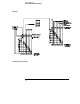
Table Of Contents
- Contents
- Title Page
- Chapter 1 Introduction to Programming
- Chapter 2 Programming Getting Started
- Chapter 3 Programming over HP-IB
- Chapter 4 Programming over RS-232-C
- Chapter 5 Programming and Documentation Conventions
- Chapter 6 Status Reporting
- Figure 6-1. Status Reporting Overview Block Diagram
- Table 6-1. Status Reporting Bit Definition
- Status Reporting Data Structures
- Status Byte Register (SBR)
- Service Request Enable Register (SRER)
- Trigger Event Register (TRG)
- Standard Event Status Register (SESR)
- Standard Event Status Enable Register (SESER)
- User Event Register (UER)
- Local Event Register (LCL)
- Operation Status Register (OPR)
- Limit Test Event Register (LTER)
- Mask Test Event Register (MTER)
- Histogram Event Register (HER)
- Arm Event Register (ARM)
- Error Queue
- Output Queue
- Message Queue
- Key Queue
- Clearing Registers and Queues
- Figure 6-3. Status Reporting Decision Chart
- Chapter 7 Installing and Using the Programmer's Reference
- Chapter 8 Programmer’s Quick Reference
- Warranty
- Index

Limit Test Event Register (LTER)
Bit 0 (COMP) of the Limit Test Event Register is set when the Limit Test
completes. The Limit Test completion criteria are set by the LTESt:RUN
command.
Bit 1 (FAIL) of the Limit Test Event Register is set when the Limit Test fails.
Failure criteria for the Limit Test are defined by the LTESt:FAIL command.
The Limit Test Event Register is read and cleared with the LTER? query.
When either the COMP or FAIL bits are set, they in turn set the LTEST bit
(bit 8) of the Operation Status Register. You can mask the COMP and FAIL
bits, thus preventing them from setting the LTEST bit, by defining a mask
using the LTEE command.
Enable Mask Value
Block COMP and FAIL 0
Enable COMP, block FAIL 1
Enable FAIL, block COMP 2
Enable COMP and FAIL 3
Status Reporting
Limit Test Event Register (LTER)
6-15