
Programming instructions

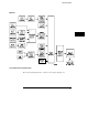
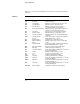
Table Of Contents
- Contents
- Title Page
- Chapter 1 Introduction to Programming
- Chapter 2 Programming Getting Started
- Chapter 3 Programming over HP-IB
- Chapter 4 Programming over RS-232-C
- Chapter 5 Programming and Documentation Conventions
- Chapter 6 Status Reporting
- Figure 6-1. Status Reporting Overview Block Diagram
- Table 6-1. Status Reporting Bit Definition
- Status Reporting Data Structures
- Status Byte Register (SBR)
- Service Request Enable Register (SRER)
- Trigger Event Register (TRG)
- Standard Event Status Register (SESR)
- Standard Event Status Enable Register (SESER)
- User Event Register (UER)
- Local Event Register (LCL)
- Operation Status Register (OPR)
- Limit Test Event Register (LTER)
- Mask Test Event Register (MTER)
- Histogram Event Register (HER)
- Arm Event Register (ARM)
- Error Queue
- Output Queue
- Message Queue
- Key Queue
- Clearing Registers and Queues
- Figure 6-3. Status Reporting Decision Chart
- Chapter 7 Installing and Using the Programmer's Reference
- Chapter 8 Programmer’s Quick Reference
- Warranty
- Index

Status Reporting Data Structures
Figure 6-2 brings together the different status reporting data structures
mentioned in this chapter and shows how they work together. To make it
possible for any of the Standard Event Status Register bits to generate a
summary bit, the bits must be enabled. These bits are enabled by using the
*ESE common command to set the corresponding bit in the Standard Event
Status Enable Register.
To generate a service request (SRQ) interrupt to an external controller, at
least one bit in the Status Byte Register must be enabled. These bits are
enabled by using the *SRE common command to set the corresponding bit in
the Service Request Enable Register. These enabled bits can then set RQS
and MSS (bit 6) in the Status Byte Register.
Status Reporting
Status Reporting Data Structures
6-5