
Programming instructions
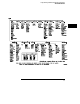
Table Of Contents
- Contents
- Title Page
- Chapter 1 Introduction to Programming
- Chapter 2 Programming Getting Started
- Chapter 3 Programming over HP-IB
- Chapter 4 Programming over RS-232-C
- Chapter 5 Programming and Documentation Conventions
- Chapter 6 Status Reporting
- Figure 6-1. Status Reporting Overview Block Diagram
- Table 6-1. Status Reporting Bit Definition
- Status Reporting Data Structures
- Status Byte Register (SBR)
- Service Request Enable Register (SRER)
- Trigger Event Register (TRG)
- Standard Event Status Register (SESR)
- Standard Event Status Enable Register (SESER)
- User Event Register (UER)
- Local Event Register (LCL)
- Operation Status Register (OPR)
- Limit Test Event Register (LTER)
- Mask Test Event Register (MTER)
- Histogram Event Register (HER)
- Arm Event Register (ARM)
- Error Queue
- Output Queue
- Message Queue
- Key Queue
- Clearing Registers and Queues
- Figure 6-3. Status Reporting Decision Chart
- Chapter 7 Installing and Using the Programmer's Reference
- Chapter 8 Programmer’s Quick Reference
- Warranty
- Index

Example 2:
OUTPUT 707;":TIMEBASE:REFERENCE CENTER ; DELAY 0.00001"
or
OUTPUT 707;":TIMEBASE:REFERENCE CENTER"
OUTPUT 707;":TIMEBASE:DELAY 0.00001"
In the first line of example 2, the “subsystem selector” is implied for the
DELAY command in the compound command. The DELAY command must be
in the same program message as the REFERENCE command, since the
program message terminator places the parser back at the root of the
command tree.
A second way to send these commands is by placing TIMEBASE: before the
DELAY command as shown in the second part of example 2.
Example 3:
OUTPUT 707;":TIMEBASE:REFERENCE CENTER ; :ANALOG1:OFFSET ’0’"
The leading colon before ANALOG1 tells the parser to go back to the root of
the command tree. The parser can then see the ANALOG1:OFFSET
command.
Programming and Documentation Conventions
The Command Tree
5-9