
Programming instructions
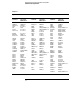
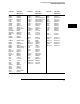
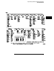
Table Of Contents
- Contents
- Title Page
- Chapter 1 Introduction to Programming
- Chapter 2 Programming Getting Started
- Chapter 3 Programming over HP-IB
- Chapter 4 Programming over RS-232-C
- Chapter 5 Programming and Documentation Conventions
- Chapter 6 Status Reporting
- Figure 6-1. Status Reporting Overview Block Diagram
- Table 6-1. Status Reporting Bit Definition
- Status Reporting Data Structures
- Status Byte Register (SBR)
- Service Request Enable Register (SRER)
- Trigger Event Register (TRG)
- Standard Event Status Register (SESR)
- Standard Event Status Enable Register (SESER)
- User Event Register (UER)
- Local Event Register (LCL)
- Operation Status Register (OPR)
- Limit Test Event Register (LTER)
- Mask Test Event Register (MTER)
- Histogram Event Register (HER)
- Arm Event Register (ARM)
- Error Queue
- Output Queue
- Message Queue
- Key Queue
- Clearing Registers and Queues
- Figure 6-3. Status Reporting Decision Chart
- Chapter 7 Installing and Using the Programmer's Reference
- Chapter 8 Programmer’s Quick Reference
- Warranty
- Index

Command Set Organization
The command set is divided into common commands, root level commands
and sets of subsystem commands. Each of the groups of commands is
described in the HP 54645A/D Oscilloscopes Programmer’s Reference,
which is supplied as an online help file for Microsoft Windows. See the
chapter "Installing and Using the Programmer’s Reference" for information on
installing and using the help file.
The commands shown use upper and lowercase letters. As an example,
AUToscale indicates that the entire command name is AUTOSCALE. To
speed up the transfer, the short form AUT is also accepted by the oscillscope.
Each command listing contains a description of the command and its
arguments and command syntax. Some commands have a programming
example.
The subsystems are listed below:
Subsystem Description
ACQuire sets the parameters for acquiring and storing data
ANALog controls the channel display and vertical or Y-axis of the oscilloscope
CALibrate provides utility commands for determining the state of the calibration
factor protection switch
CHANnel controls all oscilloscope functions associated with individual channels
or groups of channels
Common commands defined by IEEE 488.2 standard common to all instruments
DISPlay controls how waveforms, graticule, and text are displayed and written
on the screen
FUNCtion controls functions in the Measurement/Storage Module
HARDcopy provides commands to set and query the selection of hardcopy device
and formatting options
MASK controls the waveform monitoring test function available when using
the Measurement/Storage Module
MEASure selects automatic measurements to be made and controls time markers
ROOT controls many of the basic functions of the oscilloscope and reside at
the root of the command tree
SYStem controls some basic functions of the oscilloscope
TEST allows instrument self-tests to be performed via the remote interface
TIMebase controls all horizontal sweep functions
TRACe controls features used with trace memories
TRIGger controls the trigger modes and parameters for each trigger type
WAVeform provides access to waveform data
Programming and Documentation Conventions
Command Set Organization
5-3