
Programming instructions
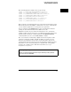
Table Of Contents
- Contents
- Title Page
- Chapter 1 Introduction to Programming
- Chapter 2 Programming Getting Started
- Chapter 3 Programming over HP-IB
- Chapter 4 Programming over RS-232-C
- Chapter 5 Programming and Documentation Conventions
- Chapter 6 Status Reporting
- Figure 6-1. Status Reporting Overview Block Diagram
- Table 6-1. Status Reporting Bit Definition
- Status Reporting Data Structures
- Status Byte Register (SBR)
- Service Request Enable Register (SRER)
- Trigger Event Register (TRG)
- Standard Event Status Register (SESR)
- Standard Event Status Enable Register (SESER)
- User Event Register (UER)
- Local Event Register (LCL)
- Operation Status Register (OPR)
- Limit Test Event Register (LTER)
- Mask Test Event Register (MTER)
- Histogram Event Register (HER)
- Arm Event Register (ARM)
- Error Queue
- Output Queue
- Message Queue
- Key Queue
- Clearing Registers and Queues
- Figure 6-3. Status Reporting Decision Chart
- Chapter 7 Installing and Using the Programmer's Reference
- Chapter 8 Programmer’s Quick Reference
- Warranty
- Index

Example Program
This program demonstrates the basic command structure used to program
the oscilloscope.
10 CLEAR 707 ! Initialize instrument interface
20 OUTPUT 707;"*RST" ! Initialize inst to preset state
30 OUTPUT 707;":TIMEBASE:RANGE 5E-4" ! Time base to 50 us/div
40 OUTPUT 707;":TIMEBASE:DELAY 0" ! Delay to zero
50 OUTPUT 707;":TIMEBASE:REFERENCE CENTER" ! Display reference at center
60 OUTPUT 707;":ANALOG1:PROBE X10" ! Probe attenuation to 10:1
70 OUTPUT 707;":ANALOG1:RANGE 1.6" ! Vertical range to 1.6 V full scale
80 OUTPUT 707;":ANALOG1:OFFSET -.4" ! Offset to -0.4
90 OUTPUT 707;":ANALOG1:COUPLING DC" ! Coupling to DC
100 OUTPUT 707;":TRIGGER:MODE NORMAL" ! Normal triggering
110 OUTPUT 707;":TRIGGER:LEVEL -.4" ! Trigger level to -0.4
120 OUTPUT 707;":TRIGGER:SLOPE POSITIVE" ! Trigger on positive slope
130 OUTPUT 707;":ACQUIRE:TYPE NORMAL" ! Normal acquisition
140 OUTPUT 707;":DISPLAY:GRID OFF" ! Grid off
150 END
•
Line 10 initializes the instrument interface to a known state.
•
Line 20 initializes the instrument to a preset state.
•
Lines 30 through 50 set the time base mode to normal with the horizontal
time at 50 µs/div with 0 s of delay referenced at the center of the graticule.
•
Lines 60 through 90 set the vertical range to 1.6 volts full scale with center
screen at -0.4 volts with 10:1 probe attenuation and DC coupling.
•
Lines 100 through 120 configure the instrument to trigger at -0.4 volts
with normal triggering.
•
Line 130 configures the instrument for normal acquisition.
•
Line 140 turns the grid off.
Programming Getting Started
Example Program
2-5