
Operating instructions

University of Saskatchewan
Electrical Engineering Laboratory Equipment Manual
Vertical Current/Div: 2 mA/div
Termination Knob (on the right side of the shelf):
Base Term: Step Gen (fully clockwise position)
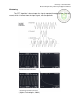
As with the 575s, before you actually switch in the transistor to the instrument,
you must make sure that the baseline is aligned properly. Using the horizontal and
vertical position controls, align the leftmost point of the baseline so that it is directly
underneath the bottom leftmost crosshair on the display.
To test a diode, the same settings as for an npn transistor are used, except the
horizontal volts/div should be reduced to 0.2 volts/div. Connect the diode to the C and
E terminals of the test pod, just as with the 575s.
To test a pnp transistor, the settings outlined above for an npn transistor are also
used, with the following two exceptions:
Collector Supply Polarity: - (PNP side)
Display: NORM pushbutton in out position (invert)
With the display inverted, the baseline is aligned to the bottom left side of the screen, as
with npn transistors. However, now the vertical axis is –I
C
, and the horizontal axis is –V
CE
. The
origin is still located at the bottom left corner of the display.