
Operating instructions

University of Saskatchewan
Electrical Engineering Laboratory Equipment Manual
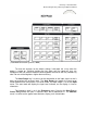
npn Transistor:
Vertical
Current/div:
1 mA/div
Horiz. Volts/div:
1 V/div
(collector)
Base Step
Generator:
Toggle switch to
Repetitive
Steps/Family
set to middle
Polarity: +
Steps/sec: 120
(top position)
Series Resistor:
220
Step Selector:
0.01 mA (10 A) per
step
Step Zero set to
middle
Short/Open
Circuit Toggle Switch
set to middle position
Collector Sweep:
0-20 V Range
Peak Volts set
to middle
Dissipation
Limiting Resistor: 100
Test Pod:
Knob set to
Emitter Grounded
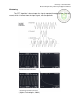
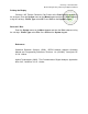
Before you flip the toggle switch on the test pod to connect your transistor to the
instrument, you must align the baseline displayed on the screen. The horizontal line
displayed on the screen is the baseline of the plot. Using the horizontal and vertical
position controls, move the baseline so that its start (its leftmost point) is aligned with
the bottom leftmost crosshair on the display. You may now flip the toggle switch on the
pod to switch in your transistor. When you are finished with a transistor, always be sure
to flip the toggle switch to the middle position before you disconnect it from the test pod.
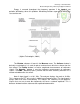
To test a diode, the same settings suggested above may be used, although the
horizontal volts/div may be reduced to 0.2 V/div. The diode is connected to the C and E
terminals of the pod, in the following manner: C E (C to anode, E to cathode).
The cathode of a diode is identified by a band.
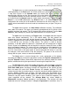
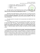
To test a pnp transistor, the same basic settings as for an npn transistor are
suggested, except for the following exceptions:
Collector sweep polarity: - (pnp)
Base step polarity: -
Baseline must be aligned so that its rightmost point falls under the top
rightmost crosshair on the display.
When a pnp transistor is measured, the I
C
vs. V
CE
characteristic will be inverted.
Remember that the origin (I
C
= 0, V
CE
= 0 point) is now in the top right hand corner of
the display.