
Operating instructions

University of Saskatchewan
Electrical Engineering Laboratory Equipment Manual
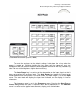
Generator status: repetitive / off / single family
Number of steps/family, adjustable from 4 – 12
Polarity +/-
Steps/sec: 120/240
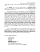
Two large knobs are located beneath the four controls mentioned above. The
one on the left selects the series resistor (with the base), while the one on the right
selects the volts or current per step, depending on its setting.
Beneath these two large knobs are a switch and a knob. The switch (on the left)
can defeat the base generator, setting the base either to a zero current (open circuit) or
a zero volts (grounded) configuration. If the switch is left in the middle position, the
base step generator is connected to the base of the transistor under test. This is the
normal configuration.
The knob controls the zero point of the step generator and should be left in the
middle position.
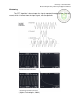
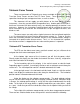
At the bottom of the instrument is the test pod where connections are made to
the transistor or diode under test. Two connection points are available; one on the left,
the other on the right. The toggle switch at the top of the middle of the pod selects
between each connection point. When the switch is in the middle position, each test
point is disconnected from the electronics within the instrument. Beneath the toggle
switch is a knob that grounds either the emitter or the base of the transistor being
tested.
To test a transistor or a diode, turn the instrument on and allow it to warm up for
a couple of minutes if it hasn’t been turned on that day. Make sure that the transistor
select toggle switch on the test pod is in the middle position, as dangerous voltages can
be present at the terminals if they are switched in. Connect your transistor, C to C, B to
B, E to E. For npn transistors, make sure the settings in the table on the next page are
selected. The settings for collector current/div, volts/div and base current/step are only
suggested starting points; you may of course alter them any way you wish.