
Operating instructions

University of Saskatchewan
Electrical Engineering Laboratory Equipment Manual
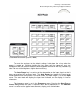
The Input menu is used to configurate the input. The Grounding key selects the
shield grounding. In the Float mode, the shields and chassis ground are connected by a
1 meg ohm resister. In the Ground mode, the shields and chassis ground are
connected by a 50 ohm resister. Do not exceed 3V on the shields in the Ground mode.
The impedance between the centre connector and the shield is 1 meg ohm. In general,
use input A and the Ground mode for single ended measurements. When the Input
Source is set to A-B (differential), the Ground mode is set automatically. In A-B
configuration the centre pins of A and B are connected to the circuit under test. The
shields are not connected to the circuit under test and do not carry a signal. They act as
shields.
The Input menu contains the Auto Offset calibration function. The calibration
takes about 10 seconds. The inputs are internally grounded and the DC offsets of the
amplifier are taken into account. The DC frequency bin will be minimized. Turn the Auto
Offset off, when making very narrow span measurements or using the source.
The Input menu also contains the Trigger mode. In the Cont mode the analyzer
takes time records continuously. This is the default mode. The time records are
triggered by the input signal with the Int (internal) mode. With Ext or TTL, the time
record is triggered from the external trigger input on the front panel. Src (source) mode
is used with the sine, two tone, or chirp sources. The source is a built in function
generator. In the Src mode the spectrum is calculated with no overlap and no trigger
circuits. Signals of the Source, that are identical in each time record, will have a stable
phase and appear triggered. The source will have a stable phase if the frequencies are
centered on the bins. The phase of the source will be arbitrary. The SR770’s source
uses the same clock as the input record. A external generator will not be in sync with
the analyzer’s clock and will drift off the bin frequency. The phase of the source will
change with the span, source, or auto offset calibration.
The Scale menu is used to change the x and y parameters of the display.
Activating the Y/Div key will lock this parameter in when the Top Ref or Bottom Ref are
adjusted. Expand X (zoom) allows detail expansion of the spectrum, about the marker
postion, without decreasing the span and thus increasing the acquisition time.
The Average menu selects the number of averages, type of averages, averaging
mode and the amount of overlap. The Average Type function selects RMS, Vector, or
Peak Hold. RMS (power averaging) averages the magnitude of the spectra only but
does not reduce the noise floor. Vector averages the complex spectrum. This will
reduce the noise floor for random signals as they are not phase coherent between time
records. Vector averaging uses a trigger. The input signal must be periodic and in
phase with the trigger. This will add in phase the real and imaginary parts of the signal.
Otherwise, they will cancel randomly. If the signal is not an exact bin frequency, the
signal magnitude will be reduced. The Average Mode key selects Linear or
Exponential averaging. Linear averaging is not continuous. The analyzer will stop
acquisition once the average function is complete. Exponential is continuous (live). A