
Operating instructions


University of Saskatchewan
Electrical Engineering Laboratory Equipment Manual
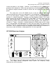
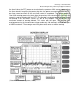
is in the 10 dB/div mode (dBv scale), and the AMPLITUDE REF LEVEL has been set to
NORMAL, then +30 is highlighted. This means that the top line of the display
corresponds to +30 dBV; the next line down would be +20 dBV and so on. The bottom
line would correspond to – 70 dBV.
The greatest accuracy in reading the level of a component is achieved when the
component is as large as possible without clipping or running off the top of the display.
When you are examining spectra that have both large and small components, it is
desirable to make the small components as large as possible in order to accurately
measure them, as mentioned above. However, if you were to adjust the INPUT
SENSITIVITY to do so, chances are that you would overload the analyzer. By adjusting
the AMPLITUDE REF LEVEL dial, you can effectively do just that, without the danger of
overloading the analyzer. The AMPLITUDE REF LEVEL dial is connected to the white
area on the INPUT SENSITIVITY knob. Turning the AMPLITUDE REF LEVEL changes
the location of the white area, and thus the scale.
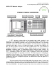
The INTENSITY and FOCUS controls do as you expect. The ADAPTIVE
SWEEP knob should always be set to the OFF position. The three DISPLAY
pushbuttons at the bottom left side of the front panel are quite self-explanatory. When
the STORE button is pushed in, a snapshot of the present display will be stored and
continually redisplayed, even if the input changes or the settings on the analyzer are
changed. If the BLANK STORE button is now pushed in, the stored waveform will not
be displayed; it is, however, still stored. The CLEAR WRITE button acts as a
reset/erase for the display.
The analyzer has a precision frequency reference within it, and this reference is
not accurate/reliable until the analyzer has a chance to warm up. Usually 15 – 30
minutes is sufficient. Once the analyzer is warmed up, you should ALWAYS check its
calibration. This calibration step is necessary to ensure that the analyzer is accurately
measuring both frequency and amplitude.
By selecting CAL on the INPUT SENSITIVITY knob, a 10 kHz internal reference
is internally connected to the analyzer’s input. See the amplitude calibration procedure
for details. Select the RESOLUTION BANDWIDTH to be used and calibrate.
Recalibrate if another resolution bandwidth is selected. You should see a large spike
at 10 kHz, and its amplitude should be such that it just touches the top grid line on the
display.
When you adjust the start/center frequency, the LED readout takes some time to
update, depending on the current sweep time/div setting. The LED is updated only
once per sweep, and trying to set the start/center frequency can be quite frustrating
because of this delay. To adjust the start/center frequency and have the LED readout
update immediately, press and hold the CLEAR WRITE button while you are making the
adjustments.