
Operating instructions

University of Saskatchewan
Electrical Engineering Laboratory Equipment Manual
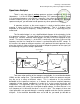
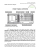
Once you have adjusted the INPUT SENSITIVITY control to its least sensitive
setting and connected an input signal, start turning up the sensitivity (clockwise) while
keeping a close watch on the MAX INPUT / OVERLOAD indicator light. The analyzer
contains some very sensitive electronics which can be very easily damaged by large
input signals, and if the MAX INPUT / OVERLOAD indicator lights, the input signals are
too large (and potentially damaging). The INPUT SENSITIVITY control should then be
turned down (counterclockwise) until the overload indicator goes off. Adjusting the
INPUT SENSITIVITY in this manner ensures that the largest components in the
spectrum are as large as possible in the display, without overloading (clipping).
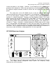
Reading the vertical scale is frequently the source of the greatest confusion
among students. If the LINEAR amplitude mode button is pushed in, the switch marked
dBv/LIN / dBm 600 should be set to the dBv/LIN position. There is a white area
behind the numbers on the INPUT SENSITIVITY knob. There are two sets of numbers,
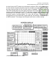
one in blue, the other black. In the linear mode, the top line of the display corresponds
to an RMS voltage, and this voltage is indicated by the blue number currently
highlighted on the INPUT SENITIVITY knob. The bottom line of the display
corresponds to 0 V. For example, if the INPUT SENSITIVITY knob has been turned to
its least sensitive scale, the analyzer is in the linear mode, and the AMPLITUDE REF
LEVEL has been set to NORMAL (more on this control below), then 20 is highlighted.
This means that the top line of the display corresponds to 20 V
rms
. The middle line
would then be 10 V
rms
, and the bottom line 0 V. Since there are 10 vertical divisions,
the vertical scale would be 2 V
rms
/div.
There are two general logarithmic scales, selectable via the switch marked dBv/LIN /
dBm 600. In the dBv mode, the display is in decibels referenced to one volt rms. The level of
a signal in dBV is given by the following formula:
Signal Level (dBV) = 20 log (V
rms
/1 V)
Where V
rms
is the rms voltage of the signal. To convert signal levels in dBV to rms volts,
Signal Level (V
rms
) = 10
(Signal level (dBV)/20)
In the dBm 600 mode, the display is in decibels referenced to a milliwatt for a 600 load.
Note: you will require an external 600 load connected in parallel with the analyzer’s input for
this mode. For this reason the dBm 600 mode is not normally used.
If either logarithmic amplitude mode is selected (10 dB/div or 1 dB/div), then you
refer to the highlighted black number on the INPUT SENSITIVITY knob. For example, if
the INPUT SENSITIVITY knob has been turned to its least sensitive scale, the analyzer