
Operating instructions

University of Saskatchewan
Electrical Engineering Laboratory Equipment Manual
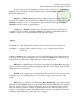
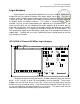
The display of the analyzer conveys a lot of information at-a-glance. At the top
left side of the screen the present sampling interval is displayed. If ―GL‖ is seen just to
the right of the sampling interval, that is an indication that glitch detection is enabled.
Much as with the HP 54600A/601A oscilloscope, in the top middle of the screen
you will find an arrow and a time. This is the time that corresponds to the middle of the
screen in the current acquisition. Just to the right of that you will find the current
time/div setting. Somewhere along the top display line you will find an upside down
solid triangle. At the bottom of the screen you will see a right-side up solid triangle
immediately beneath it. These triangles denote the t = 0 point of the acquisition.
In the top right corner of the display you will find information about the trigger
condition. Lastly, either RUN or STOP will be found to the right of that, indicating
whether the analyzer is actively acquiring data or has stopped.
Along the left edge of the display you will see a channel number adjacent to
every trace displayed on the screen. The channel labels, if turned on, will be found to
the right of the channel numbers. The labels are displayed within the waveform display
area and thus slightly decrease the waveform display area if they are on.
Immediately beneath the waveform display area, on the right side, is the activity
indicator. It graphically depicts which of the 16 channels are presently on, and whether
there is any activity on the channels that are turned on.
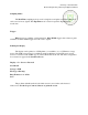
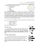
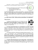
Channel Controls
The channel controls dictate which channels to display, their
position on the screen, and their labels. The large select knob may be
used to select any channel, whether it is on or off. The currently selected
channel number, if it is on, is highlighted at the left of the screen. If the
selected channel is not on, its highlighted number will appear in the top left
corner of the screen. The selected channel is also reflected by a highlight
in the channel activity graphical display at the bottom of the screen. To
turn the selected channel on or off, simply press the On/Off button. You
may relocate a selected channel (if on) by rotating the position knob.
To easily remember what channel corresponds to what signal, you may label
each. Pressing the Label button brings up the label softkey menu. One of the choices
is Labels Off/On, but the labels may also be toggled off/on by pressing the Label button
repeatedly. You may define the labels to add to the channels by pressing the Define
Labels softkey. For example, assume that you have connected the logic analyzer to a
three bit counter. You are monitoring the clock signal and the three outputs, Q0, Q1,
and Q2. If these signals are connected to channels 0 – 3, then you would want to label
channel 0 as ―Clk‖, and channels 1, 2, and 3 as Q0, Q1, and Q2 respectively.
CHANNEL
Select
Position
0 15
On
Off
Label