
Operating instructions


University of Saskatchewan
Electrical Engineering Laboratory Equipment Manual
The XY mode is very useful and is something with which you will become very familiar
in the labs. Technically, the XY mode should be named YX mode, since the Y signal is plotted
as a function of the X signal. However, the standard among scopes is to name these modes XY,
so we must stick with that same standard. The X (horizontal) signal is connected to channel 1
and the Y (vertical) signal to channel 2. The X and Y are also printed beside the channel 1 and 2
inputs on the front panel should you forget what gets connected where. While still in the Main
display mode, adjust the vertical controls of each signal so that they are as large as possible
without going off screen, and also ensure that they are each centered vertically in the display.
Make sure that each channel’s coupling and probe are also properly set. The time/div should be
adjusted so that at least one complete period is displayed horizontally.
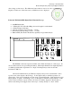
Select the XY mode to obtain a plot of signal Y vs. signal X. This display can be moved
horizontally and vertically on the screen by using the channel 1 (X position) and channel 2 (Y
position) controls. The volts/div settings for each channel found in the upper left corner of the
display tell you the voltage scale readings in the X (channel 1) and Y (channel 2) directions. To
return to the standard volts vs. time display mode, select the Main softkey in the Main/Delayed
menu.
When on, the Vernier control acts like a fine adjust for the time/div knob. Normally this
control is left off. The time reference position control is self-explanatory.
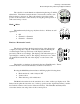
Trigger Controls
The Source menu button brings up the following items:
Channel 1
Channel 2
External Trigger (Ext)
Line
The choices are self explanatory, except perhaps for ―Line‖. Line is the
supply (line) voltage. If Ext is selected, a signal must be connected to the Ext Trigger input on
the front panel of the scope. The trigger source channel does not have to be on.
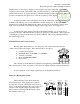
The trigger level control knob sets the trigger threshold voltage level for the selected
trigger source. When it is rotated, a solid horizontal line will briefly appear on the display to
graphically depict what voltage the trigger level is presently set to. The trigger level in volts will
be simultaneously displayed momentarily in the bottom left corner of the screen; it will also
show both the trigger source as well.
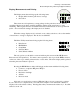
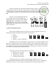
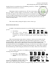
The Mode menu button brings up the following items:
Auto Level
Auto
Source
Mode
Slope
Coupling
Main
Delayed
HORIZONTAL
TRIGGER
Delay
Level
Holdoff
Time / Div
5 s
2 ns