
Operating instructions


University of Saskatchewan
Electrical Engineering Laboratory Equipment Manual
Digitizing Oscilloscopes
This document is meant to be a reference to the operation of the digitizing
oscilloscopes available in the laboratories. Major topics will be covered, but not all the
features of the scopes will be outlined here. Refer to the operations manual of the
scope you are using for detailed information. The operations manuals are available
from the technicians in 2C94.
All oscilloscopes, whether analog or digital, have similar operating principles and
similar major controls. Where they mainly differ is in their individual ―bells and whistles‖.
An oscilloscope is used to display voltage waveforms as a function of time.
These waveforms are usually cyclic in nature, and the oscilloscope performs some
processing on the waveform so that a ―stationary‖ display is shown. There are three
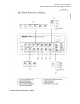
major controls that dictate the way the waveform is displayed: volts/div (vertical)
control, time/div (timebase) control, and the triggering circuitry. The volts/div control
dictates how ―big‖ or how much of the screen the waveform occupies vertically. The
time/div control dictates how many cycles (or fraction of a cycle) of the waveform are
displayed horizontally. The triggering circuitry is used to synchronize the display so that
a stationary waveform is displayed. The display may be triggered by a signal present at
any of the oscilloscope’s input channels.
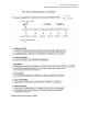
A short note about triggering and time is necessary at this point. Triggering is
actually a simple operation in principle. For instance, suppose you had a signal
generator set to output a 2 V
p-p
sine wave hooked to channel 1 of an oscilloscope and
had the oscilloscope set to trigger off of channel 1, at a level of 0 V, with a positive
slope. This means that every time the input sine wave rises through 0 V, the
oscilloscope will register a new trigger event, and uses that data to synchronize the
waveform on the screen. The time at which the trigger actually occurs is deemed to be t
= 0 by the oscilloscope. Data displayed to the left of the trigger event is called
pretrigger data; to the right, post trigger. The time/div setting controls how many cycles
of the sine wave are actually displayed on screen. In this case, the sine wave s(t) =
sin(t) V would be displayed. If the trigger level was increased to 500 mV, then s(t) =
sin(t + /4) V would be displayed. It’s important to remember that it’s still the same
sine wave, but that it is being displayed with a different t = 0 point.
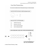
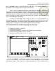
A digitizing oscilloscope is really just a fancy analog to digital converter (A/D) with
a display. The oscilloscopes in the lab all have 8 bit A/Ds, which means that they can
resolve 256 discrete voltage levels. The levels themselves are dictated by the channel
settings (mainly volts/div). Most scopes have one A/D, and each channel shares it. If
you are examining so-called ―fast‖ or ―high speed‖ signals, turn off all but one channel of
the oscilloscope (if possible) to dedicate the A/D within the scope exclusively to that
signal. Doing so will increase the sampling or resolution of that signal. Each scope also