University of Saskatchewan Electrical Engineering Laboratory Equipment Manual Analog Meters There are a wide variety of analog meters available in the labs. There are ac & dc voltmeters, ac & dc ammeters, ac & dc wattmeters, and several true rms voltmeters. They are all designed to read accurately only when they are lying flat on their back. You cannot stand these meters up, as the meter movement was not meant to have the additional burden of gravity acting on the needle.
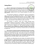
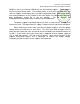
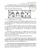
University of Saskatchewan Electrical Engineering Laboratory Equipment Manual ± 5A ± ± + 5A ± + 120 V Source - W 120 V Source Load W Load - If the load consumes little power, then the connection on the right will yield a more accurate reading. If the load consumes a moderate to high quantity of power, then the connection on the left will give a more accurate reading. As with the ammeters, most of the wattmeters have been retrofitted with a shorting switch.
University of Saskatchewan Electrical Engineering Laboratory Equipment Manual Multimeters There are a variety of both digital and analog multimeters available in the laboratories. Their operation is straightforward, so this document will be very short. The multimeters are very useful in measuring both dc and ac voltages and currents, and they all are capable of measuring resistance as well.
University of Saskatchewan Electrical Engineering Laboratory Equipment Manual Power Supplies The dc power supplies are the most often used pieces of equipment, yet they are also the most misunderstood and misused. This short document will address these misconceptions. There are a wide variety of dc power supplies in the laboratories, yet they are all very similar. All have three output connections: +, GND, and -.
University of Saskatchewan Electrical Engineering Laboratory Equipment Manual 3030D as well as the Xantrex LXD30-2/5) are dual tracking supplies. These supplies may be set to track each other. This tracking feature is not used in any laboratory, and so these supplies should always be set to their independent mode. Both Instek models have two pushbuttons on the middle of their front panel—for independent operation, both pushbuttons should be in the out position.
University of Saskatchewan Electrical Engineering Laboratory Equipment Manual Signal Generators This document is a quick reference guide to the operation of the signal generators available in the laboratories. Major functions will be covered, but some features such as their sweep operation will not, as this type of function is not used in the laboratories. Refer to the operations manual of the signal generator you are using for detailed information. These manuals are available from the technicians in 2C94.
University of Saskatchewan Electrical Engineering Laboratory Equipment Manual output is controlled via the AMPLITUDE adjust knob. If a dc offset is required, press the DC OFFSET button; the knob directly beneath it will adjust the amount of dc offset (both positive and negative offsets are possible). If you require a TTL compatible square wave, then no amplitude or offset adjustments are necessary—just take the output from the TTL OUT connector.
University of Saskatchewan Electrical Engineering Laboratory Equipment Manual The Instek FG-8016G is a low cost, low quality signal generator. For most laboratories it functions quite well, but it has performed much less than adequately in a couple of special situations. Its frequency range is 0.2 Hz – 2.1 MHz.
University of Saskatchewan Electrical Engineering Laboratory Equipment Manual The Wavetek Model 180 is an easy-to-use sig gen. Its frequency range is 0.2 Hz – 2.0 MHz. The output is taken from either the LO or HI output connector. There is a difference of 20 dB in signal level between the two. The operation of this sig gen is very similar to the others already discussed and so will not be repeated here.
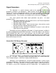
University of Saskatchewan Electrical Engineering Laboratory Equipment Manual The amplitude of the pulses is set by the AMPLITUDE range/adjust knob. A dc offset may also be added to the output pulsetrain by pulling the OFFSET knob out. The output is taken from either the POSITIVE OUTPUT or NEGATIVE OUTPUT connectors. Advance Instruments PG 58 Pulse Generator PULSE GENERATOR PG 58 ADVANCE INSTRUMENTS SUPPLY ON FREQUENCY kHz 10 100 MHz MANUAL EXT. TRIG. INPUT 1 100 1 10 5 1 0.
University of Saskatchewan Electrical Engineering Laboratory Equipment Manual ( Hewlett-Packard Company, 2000 )
University of Saskatchewan Electrical Engineering Laboratory Equipment Manual ( Hewlett-Packard Company, 2000 )
University of Saskatchewan Electrical Engineering Laboratory Equipment Manual ( Hewlett-Packard Company, 2000 )
University of Saskatchewan Electrical Engineering Laboratory Equipment Manual Some keys have a number printed in green next to them. To access the numbers, press the Enter Number key (num annunciator turns on ) and then press the keys to access the numbers. If you press the Enter Number key by accident, press the Shift key and then the Cancel key (num annunciator turns off). This generator will limit the maximum and minimum values.
University of Saskatchewan Electrical Engineering Laboratory Equipment Manual To output a 10KHz TTL waveform: Push the Square key to select the waveform. Push the following keys in order, Freq, Enter Number, 1, 0, kHz, to enter the frequency. Push the following keys in order, Ampl, Enter Number, 5, Vpp, to enter the amplitude. Push the following keys in order, Offset, Enter Number, 2, . , 5, Vpp, to enter the 2.5 VDC offset.
University of Saskatchewan Electrical Engineering Laboratory Equipment Manual To set the modulating frequency ( 10mHz to 10KHz, internal source only ), push the Shift key and then the Freq key. Adjust the frequency. The peak frequency deviation is the change in frequency, of the modulating waveform, from the carrier frequency. Push the Shift and then the Level key. Adjust the frequency deviation. To disable the frequency modulation press the Shift key and then the FM key.
University of Saskatchewan Electrical Engineering Laboratory Equipment Manual Quick Guide: Turn Power On. Push Store/Recall. If Pwr-ON is on Default, the generator was set to factory default when powered On. If Pwr-ON is on Last, the generator did not reset to factory defaults. Push the Pwr-On soft key to set it to Default. Push the Set to Defaults and Yes soft keys to set to factory defaults. The Generator should always be set to factory defaults before use. Push Utility and the Output Setup soft key.
University of Saskatchewan Electrical Engineering Laboratory Equipment Manual Digitizing Oscilloscopes This document is meant to be a reference to the operation of the digitizing oscilloscopes available in the laboratories. Major topics will be covered, but not all the features of the scopes will be outlined here. Refer to the operations manual of the scope you are using for detailed information. The operations manuals are available from the technicians in 2C94.
University of Saskatchewan Electrical Engineering Laboratory Equipment Manual has a bandwidth rating – either 60 MHz or 100 MHz. bandwidth of the analog electronics that precede the A/D. This number refers to the There is one last important point to be made about the digitizing oscilloscopes. They all have coaxial connectors (known as BNC connectors); they consist of an inner conductor and an outer conductor, which is connected to ground internal to the scope.
University of Saskatchewan Electrical Engineering Laboratory Equipment Manual capacitance of 13 pF. Each input may tolerate an absolute maximum of 400 V. The HPIB connector is found on the back left side of the scope. The display of this scope conveys much information. At the top left side of the screen you will find the channels that are on, as well as their volts/div setting and coupling. For instance, 1 2.00V 2 P5.00V means that channel 1 is set to 2 V/div and is dc coupled.
University of Saskatchewan Electrical Engineering Laboratory Equipment Manual VERTICAL Volts / Div The volts/div for each channel are adjusted using the large Volts/Div adjust knobs. Turn them counterclockwise to increase the volts/div; turn them clockwise to decrease it. The position knobs control the vertical position of the waveforms on the screen by moving the ground position of each waveform up or down.
University of Saskatchewan Electrical Engineering Laboratory Equipment Manual The XY mode is very useful and is something with which you will become very familiar in the labs. Technically, the XY mode should be named YX mode, since the Y signal is plotted as a function of the X signal. However, the standard among scopes is to name these modes XY, so we must stick with that same standard. The X (horizontal) signal is connected to channel 1 and the Y (vertical) signal to channel 2.
University of Saskatchewan Electrical Engineering Laboratory Equipment Manual Normal Single TV Auto level is the default triggering mode. It sets the trigger point to the 50% amplitude point on the selected trigger source waveform. If there is no waveform present, a baseline is displayed. Auto is a trigger mode that allows you to set the trigger threshold manually, but, like the auto level mode, it will display a baseline if the trigger conditions are not met.
University of Saskatchewan Electrical Engineering Laboratory Equipment Manual Display, Measurements and Printing Measure The Display menu button brings up the following items: Display Mode normal / peak detect / average Grid off/on Voltage Time Cursors Save / Recall Trace Setup Auto scale Display Print Utility These items are self-explanatory, except perhaps for the peak detect mode.
University of Saskatchewan Electrical Engineering Laboratory Equipment Manual When factors are on, the oscilloscope will also print extra information regarding the waveforms underneath the screen plot. Normally factors is left off. The resolution should be set low to function properly with the printers available in the labs. A variety of automatic voltage and time measurements are available through the Voltage and Time measurement menu buttons.
University of Saskatchewan Electrical Engineering Laboratory Equipment Manual other voltage or time cursor. The difference between the two cursors in volts or seconds is also displayed. In the case of the time cursors, 1/difference is also displayed.
University of Saskatchewan Electrical Engineering Laboratory Equipment Manual displayed here. If the scope is stopped, a solid octagon (stop sign) along with ―Stop‖ will be displayed. The next bit of information that you find along the top of the display is the middle graticule time readout. It displays the time to which the middle graticule corresponds. The t = 0 position is indicated by the upside down solid arrow at the top of the display.
University of Saskatchewan Electrical Engineering Laboratory Equipment Manual The horizontal menu button brings up the following items: Main / Window Zone / Window Trigger knob level / holdoff The ―Main‖ horizontal mode is the standard volts vs. time oscilloscope display mode. When the ―Window Zone‖ mode is selected, two vertical cursors are displayed on the screen. They define a window that you can use to zoom in on a feature of the waveform(s) being examined.
University of Saskatchewan Electrical Engineering Laboratory Equipment Manual The ac/dc coupling option determines whether the trigger signal is ac or dc coupled to the trigger circuitry. The noise reject option decreases the sensitivity of the trigger circuitry to help avoid false triggers on noisy waveforms. HF reject low-pass filters the trigger signal with a cutoff frequency of 80 kHz. LF reject high-pass filters the trigger signal with a cutoff of 300 kHz.
University of Saskatchewan Electrical Engineering Laboratory Equipment Manual displayed) may be set anywhere from off (minimum persistence) to infinite. Several times are selectable in-between these two extremes. The display format is normally left set to YT; this is the normal volts vs. time display of the scope. When you wish to display one waveform vs. another, set the format to XY. When in the XY mode, channel 1 is the X (horizontal) waveform, and channel 2 is the Y (vertical) waveform.
University of Saskatchewan Electrical Engineering Laboratory Equipment Manual here are self-explanatory. To move the cursors, use the channel 1 & 2 vertical position controls. When either the voltage or time cursors are active, the position of each cursor as well as the difference between them (in either volts or seconds) will be displayed at the right side of the display. In the case of the time cursors, 1/difference will also be displayed.
University of Saskatchewan Electrical Engineering Laboratory Equipment Manual The RS232 setup softkey reveals another set of options. Leave all fields set to their default values (press the ―Set to defaults‖ softkey); these default values are sufficient for your needs. Math Menu Pressing the math menu button will automatically switch the scope to the math function currently selected. There are three major functions: addition, subtraction, and FFT (fast fourier VERTICAL transform or spectrum analysis).
University of Saskatchewan Electrical Engineering Laboratory Equipment Manual Rectangular Pulses or transients Special purpose window for waveforms that do not have discontinuities (same as no window) The FFT zoom level (X1 / X2 / X5 / X10) changes the horizontal magnification of the FFT display. The FFT display is calibrated in dBV (decibels referenced to one volt rms).
University of Saskatchewan Electrical Engineering Laboratory Equipment Manual Tektronix TDS 3012B Oscilloscope FFT Math Function This function converts an oscilloscope time-domain waveform into its frequency spectrum. Waveforms with a D.C. component may cause errors in FFT magnitudes. Push the Save/Recall button, Recall Factory Setup button and the Confirm button. Connect the source to the scope and display the time-domain waveform.
University of Saskatchewan Electrical Engineering Laboratory Equipment Manual If I want a 100 KHz BW which is 10 KHz / div. 100 KHZ (nyquist) X 2 = 200 KHz sample rate nearest higher sample rate 250 KS/s Nyquist = 250 KHz / 2 = 125 KHz BW 125 MHz / 10 div = 12.5 KHz / div freq. resolution = 12.5 kHz / 50 = 250 Hz. Agilent 54621D Mixed – Signal Oscilloscope The 54621D is a combination oscilloscope and logic analyzer. The digital section on the front panel is the logic analyzer part of the unit.
University of Saskatchewan Electrical Engineering Laboratory Equipment Manual This unit, along with other scopes and analyzers, should be reset to factory default settings before using. Press the Save/Recall button and then the Default Setup button to reset. This unit, along with other scopes and analyzers, has an Auto-Scale button. Auto-Scale automatically configures the scope to display the signals at its inputs.
University of Saskatchewan Electrical Engineering Laboratory Equipment Manual Holdoff keeps a trigger from occurring until the amount of time set has passed since the last trigger. Used, on a repeating pattern of a waveform, to trigger on the same edge of the pattern. Edge triggers on a falling or rising transition. Pulse Width triggers after a time set pulse width has occurred. Pattern trigger is a logical AND of the channels. Channels can be specified high, low, or don’t care (X).
University of Saskatchewan Electrical Engineering Laboratory Equipment Manual affect the resolution of the display. Always use the max. volts/div and sweep speed (time/div) that fits on the display. The Delayed sweep window is used to expand the waveform ( zoom ). The Delayed window shows a portion of the main sweep. The display is divided in two, showing the main and expanded portion. Peak Detection acquisition mode provides more detail when expanding the waveform.
University of Saskatchewan Electrical Engineering Laboratory Equipment Manual Agilent MSO6014A Mixed Signal Oscilloscope The 6014A is a combination oscilloscope and logic analyzer. The digital section on the front panel is the logic analyzer part of the unit. The analog section on the front panel is the oscilloscope part of the unit. The oscilloscope section is labeled analog and refers to the type of input signal.
University of Saskatchewan Electrical Engineering Laboratory Equipment Manual Main / Delayed menu Main is the normal viewing mode for the display. Delayed mode expands the main view. In Delayed mode the top half of the display shows the main sweep and the bottom half shows the delayed sweep. The delayed sweep is a magnified portion of the main sweep. The magnified portion is adjustable using the Horizontal controls.
University of Saskatchewan Electrical Engineering Laboratory Equipment Manual At slow sweep speeds, the sampling rate decreases due to an increase in acquisition time. Sampling is faster then what is required to fill the memory. Push the Main / Delayed key to display the sampling rate. Display key > Infinite Persist. The display is updated with new acquisitions and old acquisitions are displayed in gray. Persistence is limited to the display area and not memory.
University of Saskatchewan Electrical Engineering Laboratory Equipment Manual Logic Analyzer ( Digital Channels ) The Logic Analyzer cable connects to the rear panel. Be Careful not to physically Stress the cable. Route the cable around the side of the scope leaving plenty of slack at the rear of the scope. Turn off the analog channels not in use. Push the D15 Thru D0 key. Turn off the digital channels not used.
University of Saskatchewan Electrical Engineering Laboratory Equipment Manual Agilent DSO3102A Oscilloscope The introduction part of the Digitizing Oscilloscopes in the Equipment Manual should be reviewed for basic theory operation. The controls for the 3102A are similar to the HP 54601 oscilloscope. Refer to this section in the Equipment Manual for an explanation of the operation and the controls. This section is a supplement to the previous section mentioned.
University of Saskatchewan Electrical Engineering Laboratory Equipment Manual Sampling Modes The Real Time sampling mode is used for single shot and pulse waveforms. This mode can be used for most signals. The Equ-Time mode is used for repetitive high frequency waveforms. Trigger Edge triggers on a falling or rising transition. Pulse Width triggers after a time set pulse width has occurred. Video trigger is used for video signals.
University of Saskatchewan Electrical Engineering Laboratory Equipment Manual 3000 Series Scope Connect Software This software interfaces the scope to a computer. The GUI displays the scope screen and controls. The scope controls can be adjusted form the GUI. Connect a cable from the USB – B port on the back of the scope to the USB –A port on the front of the PC. Start / programs / Electrical Engineering / Lab Equipment / Agilent DSO3000 Scope. Click on the Connect to Oscilloscope icon in the tool bar.
University of Saskatchewan Electrical Engineering Laboratory Equipment Manual Logic Analyzers Logic analyzers are specialized equipment that are very similar to oscilloscopes, except that they are tailored to analyze and display digital signals only. They are, in essence, simply multiple channel oscilloscopes that only determine whether a channel is logic high or low. Their power comes from the fact that they can be set to trigger off of multiple events on different channels.
University of Saskatchewan Electrical Engineering Laboratory Equipment Manual The display of the analyzer conveys a lot of information at-a-glance. At the top left side of the screen the present sampling interval is displayed. If ―GL‖ is seen just to the right of the sampling interval, that is an indication that glitch detection is enabled. Much as with the HP 54600A/601A oscilloscope, in the top middle of the screen you will find an arrow and a time.
University of Saskatchewan Electrical Engineering Laboratory Equipment Manual Once the Define Labels softkey is pressed, a label choice box is displayed on the screen along with the following new softkeys: Delete Character Insert Space Copy Position Assign Label Previous Menu These softkeys are self-explanatory. To assign ―Clk‖ to channel 0, first make sure that channel 0 is selected. Then using the Entry knob on the front panel, scroll to ―Clk‖ from the list of labels on the screen.
University of Saskatchewan Electrical Engineering Laboratory Equipment Manual The time/div (or timebase) is adjusted by the large Time/Div knob. Turn it counterclockwise to increase the timebase, clockwise to decrease it. Pressing the Main/Delayed menu button will bring up the following items: Horizontal Mode Main/Delayed Time Reference Left / Center / Right Vernier Off/On The Main horizontal mode is the standard signal high/low vs. time logic analyzer display mode.
University of Saskatchewan Electrical Engineering Laboratory Equipment Manual The Adv (advanced) trigger menu button allows you to specify complex triggering criteria. As the advanced trigger mode will not be necessary to complete the labs, it will not be explained here. Refer to the operations manual should you need to use this feature.
University of Saskatchewan Electrical Engineering Laboratory Equipment Manual Spectrum Analyzer There is only one type of analog spectrum analyzer available for use in the laboratories. It is the HP 3580A Spectrum Analyzer. This spectrum analyzer is limited in its maximum frequency—only 50 kHz. However, it has some nice features and is an excellent teaching aid in that once you understand how to operate this particular spectrum analyzer, you will know how to operate any other spectrum analyzer.
University of Saskatchewan Electrical Engineering Laboratory Equipment Manual resolve two peaks in the display. However, if the frequency of the second signal generator were reduced to 1.2 kHz, then you would only see one peak on the display— the spectrum analyzer wouldn’t be able to resolve the two signals into two distinct peaks. The sweep time of the HP 3580A may be set by the operator, but newer spectrum analyzers do not have this adjustment, as the sweep time is automatically set.
University of Saskatchewan Electrical Engineering Laboratory Equipment Manual The display of the analyzer may be set to start or center modes, as indicated by the switch with STR and CTR above it. Depending on this switch, the LED display indicates either the start frequency in Hz, corresponding to the leftmost line on the display, or the center frequency in Hz, corresponding to the center line on the display.
University of Saskatchewan Electrical Engineering Laboratory Equipment Manual Once you have adjusted the INPUT SENSITIVITY control to its least sensitive setting and connected an input signal, start turning up the sensitivity (clockwise) while keeping a close watch on the MAX INPUT / OVERLOAD indicator light.
University of Saskatchewan Electrical Engineering Laboratory Equipment Manual is in the 10 dB/div mode (dBv scale), and the AMPLITUDE REF LEVEL has been set to NORMAL, then +30 is highlighted. This means that the top line of the display corresponds to +30 dBV; the next line down would be +20 dBV and so on. The bottom line would correspond to – 70 dBV.
University of Saskatchewan Electrical Engineering Laboratory Equipment Manual Amplitude Calibration Procedure For operation on the 10Hz, 30Hz, 100Hz, or 300Hz resolution bandwidth. (a) Turn the instrument on and allow 20 minutes for warm up. (b) Set the 3580A controls as follows: Display…………………………………………………….Store and Blank Store out Amplitude Mode…………………………………………………..…Log 10dB/division Amplitude Ref Level…………………………………………………………….Normal dBV / Lin – dBm Switch………………………………………….
University of Saskatchewan Electrical Engineering Laboratory Equipment Manual Printing the Display The HP 3580A is an analog spectrum analyzer and cannot directly print to the printers available in the laboratories. However, you can hook the analyzer up to an Oscilloscope, and print the spectra from there. On the back of the analyzer are a number of connectors. The ones marked RECORDER X-AXIS and Y-AXIS are the ones you will need. These outputs are meant for printing to an old-fashioned pen plotter.
University of Saskatchewan Electrical Engineering Laboratory Equipment Manual The output of your network is then connected to the input of the analyzer. In one simple step, this allows you to measure the amplitude response of the network as a function of frequency. This is opposed to the long and arduous alternative method whereby you connect a signal generator to the network and monitor the input and output levels of the waveforms with an oscilloscope as you select frequencies.
University of Saskatchewan Electrical Engineering Laboratory Equipment Manual SR770 FFT Network Analyzer ( Standford Research Systems, 2000 ) A FFT spectrum analyzer takes a time domain input signal, samples it and digitalizes it ( analog/digital converter ). The digital data samples ( time record ) are converted to the frequency spectrum using the fast fourier transform. The maximum frequency span of the SR770 is 0Hz to 100KHz. This FFT processor displays 400 frequency points (bins).
University of Saskatchewan Electrical Engineering Laboratory Equipment Manual the time it takes the FFT processor to calculate the spectrum. With narrow spans, where the time record is long then the processing time, the processor would calculate one FFT per time record and wait till the next time record is completed. The update would be slow. With overlap processing, data from the previous time record and the current time record is used to calculate the next FFT.
University of Saskatchewan Electrical Engineering Laboratory Equipment Manual ( Standford Reasearch Systems, 2000 ) To reset the analyzer, to the default settings, hold down the < key when the power is turned on. Continue holding the key down until the power-on tests are completed. Wait 30 seconds between switching power off and on with any cathode ray tube. Do not set the brightness higher then necessary.
University of Saskatchewan Electrical Engineering Laboratory Equipment Manual Windowing The FFT algorithm is based upon the signal repeated throughout time. The time record, which is formed from the input signal, must be periodic.
University of Saskatchewan Electrical Engineering Laboratory Equipment Manual Energy is smeared throughout the frequency spectrum if the signal is not periodic. Windowing solves this problem. Windowing functions taper off to zero at the start and the end. ( Agilent Technologies, 2000 ) The Window submenu is found in the Measure menu. The Uniform window is basically no windowing. It is used for pulses and transients which are shorter then the time record.
University of Saskatchewan Electrical Engineering Laboratory Equipment Manual The Input menu is used to configurate the input. The Grounding key selects the shield grounding. In the Float mode, the shields and chassis ground are connected by a 1 meg ohm resister. In the Ground mode, the shields and chassis ground are connected by a 50 ohm resister. Do not exceed 3V on the shields in the Ground mode. The impedance between the centre connector and the shield is 1 meg ohm.
University of Saskatchewan Electrical Engineering Laboratory Equipment Manual large number of averages, in the exponential mode, will not capture any changes in the signal. The SOURCE menu selects the output waveform. The Configure Source submenu sets the parameters. The 2-Tone waveform is the sum of two pure sine waves for intermodulation distortion tests. The Chirp source provides an equal amplitude sine wave at each bin of the span. The phases of the sine waves are set so that they do not add in phase.
University of Saskatchewan Electrical Engineering Laboratory Equipment Manual Printing the Display Connect a HP Thinkjet Centronics Port Printer to the Print Port on the back of the analyzer. Enter the System menu on the Menu keypad and then the Print submenu using the soft keys. Printer Type select HP. Press Print on the System keypad. Save to 3.5 Disc. Enter the System menu on the Menu keypad and then the Print submenu using the soft keys. Printer Type select File. Press Print on the System keypad.
University of Saskatchewan Electrical Engineering Laboratory Equipment Manual Tektronix Curve Tracers There are two models of Tektronix curve tracers available in 2C80: two Tek 575 Transistor Curve Tracers and one Tek 577 Curve Tracer. These instruments greatly speed the checking of npn and pnp transistors, as well as diodes. This document will not supply you with pictures of the front panels of these instruments, since they are too difficult to reproduce here.
University of Saskatchewan Electrical Engineering Laboratory Equipment Manual Generator status: repetitive / off / single family Number of steps/family, adjustable from 4 – 12 Polarity +/Steps/sec: 120/240 Two large knobs are located beneath the four controls mentioned above. The one on the left selects the series resistor (with the base), while the one on the right selects the volts or current per step, depending on its setting. Beneath these two large knobs are a switch and a knob.
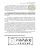
University of Saskatchewan Electrical Engineering Laboratory Equipment Manual npn Transistor: Vertical Current/div: Base Step Generator: 1 mA/div Toggle switch to Repetitive Steps/Family set to middle Polarity: + Steps/sec: 120 (top position) Series Resistor: 220 Step Selector: 0.01 mA (10 A) per step Step Zero set to middle Short/Open Circuit Toggle Switch set to middle position Horiz.
University of Saskatchewan Electrical Engineering Laboratory Equipment Manual Tektronix 577 Curve Tracer The 577 is the newest curve tracer in our inventory, and it is a little more intimidating than its older counterparts, the 575s. However, its operation is just as straightforward as it has the same basic controls as the 575s. The power switch on this instrument is difficult to spot. It is located to the right of the bottom corner of the display.
University of Saskatchewan Electrical Engineering Laboratory Equipment Manual Vertical Current/Div: 2 mA/div Termination Knob (on the right side of the shelf): Base Term: Step Gen (fully clockwise position) As with the 575s, before you actually switch in the transistor to the instrument, you must make sure that the baseline is aligned properly.