
User`s guide


53220A/53230A User’s Guide 127
53220A/53230A Input Signal Conditioning 4
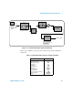
Figure 4-2. Using AC Coupling to Reach Trigger Points.
Settling Time Between DC and AC Coupling
There is an inherent settling time when changing from DC to AC coupling. As a
measure of this time, a signal with a 5V DC component (DC coupled) will typi-
cally center around 0V (AC coupled) in one second.
Coupling Example
//period measurement of expected 10 MHz signal,
//maximum resolution, use channel 1
CONF:PER 0.1E-6,MAX,(@1)
INP:COUP AC //set AC coupling
Bandwidth Limiting (Low-Pass) Filter
For measurement applications of 100 kHz or less, a 100 kHz low-pass filter can
V
U
V
L
V
C
V
U
V
L
0V
AC coupling
0V
DC coupling
V
C
programmed trigger level
}
}
Hysteresis window
trigger point
reset point
input signal with DC offset