
User`s guide


53220A/53230A User’s Guide 121
53220A/53230A Input Signal Conditioning 4
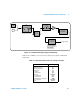
Figure 4-1. 53220A/53230A Input Signal Conditioning.
Table 4-1 is a summary of power-on/reset values for the signal conditioning.
parameters.
Table 4-1. Input Channel Reset/Preset Settings Summary.
Threshold Level
and Sensitivity
Input
AC Coup ling
trigger / gating
INPut{1|2}:COUPling
INPut{1|2}:IMPedance
INPut{1|2}:PROTection?
INPut{1|2}:PROTection:CLEar
INPut{1|2}:LEVel{1|2}
SYSTem:ALEVel:FREQuency
INPut{1|2}:LEVel:AUTO
INPut{1|2}:LEVel{1|2}:RELative
INPut3:BURSt:LEVel
INPut{1|2}:NREJect
INPut{1|2}:SLOPe{1|2}
Selectable
100 kHz
Low-Pass Filter
INPut{1|2}:FILTer
Range
Selection
INPut{1|2}:RANGe
INPut{1|2}:PROBe
Auto
Cal
Buffer
DC Coupling
50W
1MW
Input
Protection
Parameter
Setting
Impedance
Range (1:1 probe)
Range (10:1) probe
Probe factor
Coupling
Low pass filter
Auto-level
Level (absolute)
Level (relative)
Pulse Envelope (channel 3)
Noise Rejection
Slope
1 MΩ
5V
50V
1:1
AC
Off
Enabled
0.0V
50%
-6 dB
Disabled
Positive