
Specifications


Table Of Contents
- Agilent 53210A/53220A/53230A 350 MHz Universal Frequency Counter/ Timer
- Assembly Level Service Guide
- Performance Tests
- Introduction
- Power-On Test
- Self-Test (Q)
- Agilent 53210A/53220A/53230A Operational Verification
- Agilent 53210A/53220A/53230A Complete Performance Tests
- Test 1: (Q) Absolute Time Base
- Test 2: (Q) Frequency Accuracy - Channels 1 and 2
- Test 3: Single Period
- Test 4: (Q) Pulse Width
- Test 5: (Q) Time Interval
- Test 6a: (Q) Frequency Accuracy - Channel 2/3, Option 106 (6 GHz Microwave Channel)
- Test 6b: (Q) Frequency Accuracy - Channel 2/3, Option 115 (15 GHz Microwave Channel)
- Test 7a: (Q) Pulse Burst Frequency - 53230A Channel 3 Option 150 With Option 106
- Test 7c: (Q) Pulse Burst Frequency - 53230A Channel 3 Option 150 With Option 115
- Agilent 53210A/53220A/53230A Operational Verification and Performance Test Record
- Agilent 53210A/53220A/53230A Performance Test Record (Tests 1 to 7)
- Service
- Introduction
- Returning the Instrument to Agilent Technologies for Service
- About the Agilent 53210A/53220A/53230A Calibration Menu
- The Agilent 53210A/53220A/53230A Calibration Procedures
- Equipment Required
- Determine the Counter Firmware Version
- Calibration Cycle
- Calibration String:
- Internal Reference Oscillator Calibration
- Summary of Oscillator Calibration Procedure:
- Remote Oscillator Calibration Summary:
- Voltage Calibration (Internal DACs)
- Option 106 Microwave Channel Frequency Calibration
- Option 115 Microwave Channel Frequency Calibration
- Internal Auto-Calibration
- To View the Calibration Count
- Resetting the Security Code to a Null
- Pre-Troubleshooting Information
- Troubleshooting the Counter
- Unit is Inoperative
- Unit Fails Self-Test
- Power Supply Check
- Checking the Battery and Battery Charger
- Battery Operation
- Preliminary Steps
- Testing the battery
- Normal Battery Operation
- When the battery is enabled and the counter is not connected to AC power, the battery is discharged at approximately 30% of full initial capacity per day. When the battery is disabled and not connected to AC power, the battery is discharged at approx...
- Remote Battery Commands
- Performing The Counter Self-Test
- To Determine the Counter Firmware Version
- Reseat the Boards
- Re-Run the Counter Self Test
- Error Messages
- Replacing Assemblies
- Introduction
- Tools Required
- To Remove the Cover and Rear Bezel
- To Remove the Internal DC Battery Assembly (Option 300)
- To Remove the GPIB Assembly
- To Remove a 6.0 GHz or 15.0 GHz Microwave Channel Assembly (Options 106/115)
- To Remove the Processor Board
- To Remove the Front Panel Assembly
- To Remove the Motherboard
- To Remove the AC Power Supply Assembly
- Retrofitting Options
- Introduction
- To Retrofit Ultra-High Stability Timebase (Option 010)
- To Retrofit the GPIB Connector
- To Retrofit the Internal Battery DC Power (Option 300)
- To Retrofit the 53210A (Channel 1) or 53220A/53230A (Channels 1/2) Rear Panel Inputs (Option 201)
- To Retrofit the 53210A Channel 2 Front Panel Input (Option 106 or Option 115, plus Front Panel Option 202)
- To Retrofit the 53210A Channel 2 Rear Panel Input, 6.0 GHz (Option 106) or 15.0 GHz (Option 115) plus Rear Panel Option 203
- To Retrofit the 53220A/53230A Channel 3 Input, 6.0 GHz (Option 106) or 15.0 GHz (Option 115) plus Front Panel Option 202
- To Retrofit the 53220A/53230A Channel 3 Input, 6.0 GHz (Option 106) or 15.0 GHz (Option 115) plus Rear Panel Option 203
- To Retrofit Option 150 (Pulse Microwave Measurements) for the 53230A
- Replaceable Parts
- Backdating
4 Assembly Level Service Guide
Safety Notices
CAUTION
A CAUTION notice denotes a hazard. It
calls attention to an operating procedure,
practice, or the like that, if not correctly per-
formed or adhered to, could result in dam-
age to the product or loss of important data.
Do not proceed beyond a CAUTION notice
until the indicated conditions are fully under-
stood and met.
WARNING
A WARNING notice denotes a hazard. It
calls attention to an operating procedure,
practice, or the like that, if not correctly
performed or adhered to, could result in
personal injury or death. Do not proceed
beyond a WARNING notice until the indi-
cated conditions are fully understood
and met.
Safety Symbols
WARNING
Do not connect the input channels of the
53210A/53220A/53230A to AC line-volt-
age mains or to circuits derived from AC
mains. The instrument must be used in
CAT I (isolated from mains) applications
only. Do not use in other IEC Measure-
ment Category (CAT II, CAT III, or CAT IV)
applications. Failure to observe these
precautions may result in electric shock
and serious personal injury.
WARNING
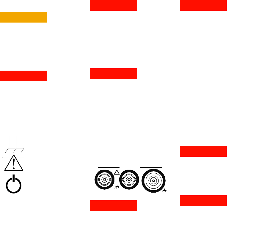
The BNC shells of the input terminals are
connected to the instrument chassis.
Verify signal polarity before making any
connections to the input terminals.
Protection Limits
The Agilent 53210A/53220A/53230A 350
MHz Universal Counter provides protection
circuitry to prevent damage to the instru-
ment and to protect against the danger of
electric shock, provided the Protection Lim-
its are not exceeded and the instrument is
properly grounded. To ensure safe operation
of the instrument, do not exceed the Protec-
tion Limits defined on the front panel:
WARNING
During battery operation, the maximum
measured signal supplied by the user is
+
42V.
WARNING
Product Options 201/202 add parallel
Channel 1 and Channel 2 inputs to the
rear panel of the instrument. Signals on
the center conductor of either panel’s
channel BNCs are also present on the
corresponding center conductor of the
BNC on the opposite panel.
Installing the Instrument
The Agilent 53210A/53220A/53230A oper-
ates in the following line-voltage ranges:
100 - 240V, 50-60 Hz
100 - 127V, 440 Hz
90 VA Max
Instrument ventilation is through the sides
and rear. Do not obstruct the ventilation
holes in any of these locations.
Battery Operation
When operating the 53210A, 53220A or
53230A under battery power (Option 300),
failure to observe the following warnings
may result in damage to the instrument,
electric shock, and serious personal injury:
WARNING
Connect the instrument chassis to earth
ground during battery operation to mini-
mize shock hazard. Any interruption or
disconnection of the protective earth ter-
minal will cause a potential shock hazard
that could result in personal injury.
WARNING
Under battery power, the instrument
chassis may float to the potential of the
measured signal supplied by the user.
Chassis Ground
Refer to manual for additional
safety information.
Standby Power. Unit is not com-
pletely disconnected from AC
mains when power switch is in
standby position.
CAT I
IEC Measurement Category I. Do
NOT connect inputs to AC mains
or to circuits derived from AC
mains.
1 Watt Max into 50W
!
Channel / Setup