
Specifications


Table Of Contents
- Agilent 53210A/53220A/53230A 350 MHz Universal Frequency Counter/ Timer
- Assembly Level Service Guide
- Performance Tests
- Introduction
- Power-On Test
- Self-Test (Q)
- Agilent 53210A/53220A/53230A Operational Verification
- Agilent 53210A/53220A/53230A Complete Performance Tests
- Test 1: (Q) Absolute Time Base
- Test 2: (Q) Frequency Accuracy - Channels 1 and 2
- Test 3: Single Period
- Test 4: (Q) Pulse Width
- Test 5: (Q) Time Interval
- Test 6a: (Q) Frequency Accuracy - Channel 2/3, Option 106 (6 GHz Microwave Channel)
- Test 6b: (Q) Frequency Accuracy - Channel 2/3, Option 115 (15 GHz Microwave Channel)
- Test 7a: (Q) Pulse Burst Frequency - 53230A Channel 3 Option 150 With Option 106
- Test 7c: (Q) Pulse Burst Frequency - 53230A Channel 3 Option 150 With Option 115
- Agilent 53210A/53220A/53230A Operational Verification and Performance Test Record
- Agilent 53210A/53220A/53230A Performance Test Record (Tests 1 to 7)
- Service
- Introduction
- Returning the Instrument to Agilent Technologies for Service
- About the Agilent 53210A/53220A/53230A Calibration Menu
- The Agilent 53210A/53220A/53230A Calibration Procedures
- Equipment Required
- Determine the Counter Firmware Version
- Calibration Cycle
- Calibration String:
- Internal Reference Oscillator Calibration
- Summary of Oscillator Calibration Procedure:
- Remote Oscillator Calibration Summary:
- Voltage Calibration (Internal DACs)
- Option 106 Microwave Channel Frequency Calibration
- Option 115 Microwave Channel Frequency Calibration
- Internal Auto-Calibration
- To View the Calibration Count
- Resetting the Security Code to a Null
- Pre-Troubleshooting Information
- Troubleshooting the Counter
- Unit is Inoperative
- Unit Fails Self-Test
- Power Supply Check
- Checking the Battery and Battery Charger
- Battery Operation
- Preliminary Steps
- Testing the battery
- Normal Battery Operation
- When the battery is enabled and the counter is not connected to AC power, the battery is discharged at approximately 30% of full initial capacity per day. When the battery is disabled and not connected to AC power, the battery is discharged at approx...
- Remote Battery Commands
- Performing The Counter Self-Test
- To Determine the Counter Firmware Version
- Reseat the Boards
- Re-Run the Counter Self Test
- Error Messages
- Replacing Assemblies
- Introduction
- Tools Required
- To Remove the Cover and Rear Bezel
- To Remove the Internal DC Battery Assembly (Option 300)
- To Remove the GPIB Assembly
- To Remove a 6.0 GHz or 15.0 GHz Microwave Channel Assembly (Options 106/115)
- To Remove the Processor Board
- To Remove the Front Panel Assembly
- To Remove the Motherboard
- To Remove the AC Power Supply Assembly
- Retrofitting Options
- Introduction
- To Retrofit Ultra-High Stability Timebase (Option 010)
- To Retrofit the GPIB Connector
- To Retrofit the Internal Battery DC Power (Option 300)
- To Retrofit the 53210A (Channel 1) or 53220A/53230A (Channels 1/2) Rear Panel Inputs (Option 201)
- To Retrofit the 53210A Channel 2 Front Panel Input (Option 106 or Option 115, plus Front Panel Option 202)
- To Retrofit the 53210A Channel 2 Rear Panel Input, 6.0 GHz (Option 106) or 15.0 GHz (Option 115) plus Rear Panel Option 203
- To Retrofit the 53220A/53230A Channel 3 Input, 6.0 GHz (Option 106) or 15.0 GHz (Option 115) plus Front Panel Option 202
- To Retrofit the 53220A/53230A Channel 3 Input, 6.0 GHz (Option 106) or 15.0 GHz (Option 115) plus Rear Panel Option 203
- To Retrofit Option 150 (Pulse Microwave Measurements) for the 53230A
- Replaceable Parts
- Backdating
Chapter 6 Backdating
Introduction
248 Assembly-Level Service Guide
Introduction
This chapter contains information necessary to adapt this service guide to
older instruments.
The backdating information includes the following:
• Backdating Firmware
• Procedure Changes
• Backdating Hardware
• Backdating Specifications
Serial Numbers
NOTE The serial number prefix for your counter is the first 5 character
positions in the serial number shown on the counter (for example:
MY500
00125). The counter serial number suffix (for example:
MY50000125
) is the production number of the counter. The whole
number (MY50000125) is the actual serial number of the counter.
See Figure 6-1.
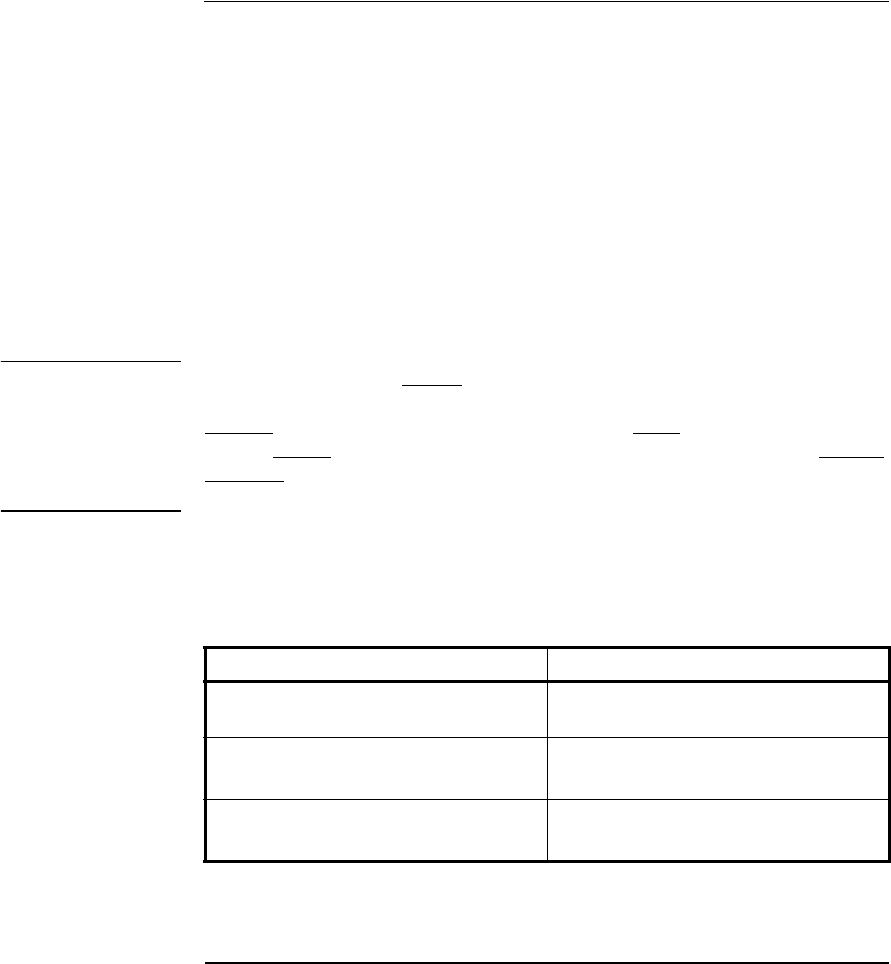
This guide applies directly to Counters with the serial prefixes listed in
Table 6-1. (See also Figure 6-1.)
Table 6-1. Instruments this Guide Directly Applies To
Instrument Serial Prefix Number
Agilent 53210A 350 MHz 10-Digit RF
Counter
MY500 or SG500
Agilent 53220A 350 MHz 10-Digit
Universal Counter
MY500 or SG500
Agilent 53230A 350 MHz 12-Digit
Universal Counter
MY500 or SG500