
Specifications


Table Of Contents
- Agilent 53210A/53220A/53230A 350 MHz Universal Frequency Counter/ Timer
- Assembly Level Service Guide
- Performance Tests
- Introduction
- Power-On Test
- Self-Test (Q)
- Agilent 53210A/53220A/53230A Operational Verification
- Agilent 53210A/53220A/53230A Complete Performance Tests
- Test 1: (Q) Absolute Time Base
- Test 2: (Q) Frequency Accuracy - Channels 1 and 2
- Test 3: Single Period
- Test 4: (Q) Pulse Width
- Test 5: (Q) Time Interval
- Test 6a: (Q) Frequency Accuracy - Channel 2/3, Option 106 (6 GHz Microwave Channel)
- Test 6b: (Q) Frequency Accuracy - Channel 2/3, Option 115 (15 GHz Microwave Channel)
- Test 7a: (Q) Pulse Burst Frequency - 53230A Channel 3 Option 150 With Option 106
- Test 7c: (Q) Pulse Burst Frequency - 53230A Channel 3 Option 150 With Option 115
- Agilent 53210A/53220A/53230A Operational Verification and Performance Test Record
- Agilent 53210A/53220A/53230A Performance Test Record (Tests 1 to 7)
- Service
- Introduction
- Returning the Instrument to Agilent Technologies for Service
- About the Agilent 53210A/53220A/53230A Calibration Menu
- The Agilent 53210A/53220A/53230A Calibration Procedures
- Equipment Required
- Determine the Counter Firmware Version
- Calibration Cycle
- Calibration String:
- Internal Reference Oscillator Calibration
- Summary of Oscillator Calibration Procedure:
- Remote Oscillator Calibration Summary:
- Voltage Calibration (Internal DACs)
- Option 106 Microwave Channel Frequency Calibration
- Option 115 Microwave Channel Frequency Calibration
- Internal Auto-Calibration
- To View the Calibration Count
- Resetting the Security Code to a Null
- Pre-Troubleshooting Information
- Troubleshooting the Counter
- Unit is Inoperative
- Unit Fails Self-Test
- Power Supply Check
- Checking the Battery and Battery Charger
- Battery Operation
- Preliminary Steps
- Testing the battery
- Normal Battery Operation
- When the battery is enabled and the counter is not connected to AC power, the battery is discharged at approximately 30% of full initial capacity per day. When the battery is disabled and not connected to AC power, the battery is discharged at approx...
- Remote Battery Commands
- Performing The Counter Self-Test
- To Determine the Counter Firmware Version
- Reseat the Boards
- Re-Run the Counter Self Test
- Error Messages
- Replacing Assemblies
- Introduction
- Tools Required
- To Remove the Cover and Rear Bezel
- To Remove the Internal DC Battery Assembly (Option 300)
- To Remove the GPIB Assembly
- To Remove a 6.0 GHz or 15.0 GHz Microwave Channel Assembly (Options 106/115)
- To Remove the Processor Board
- To Remove the Front Panel Assembly
- To Remove the Motherboard
- To Remove the AC Power Supply Assembly
- Retrofitting Options
- Introduction
- To Retrofit Ultra-High Stability Timebase (Option 010)
- To Retrofit the GPIB Connector
- To Retrofit the Internal Battery DC Power (Option 300)
- To Retrofit the 53210A (Channel 1) or 53220A/53230A (Channels 1/2) Rear Panel Inputs (Option 201)
- To Retrofit the 53210A Channel 2 Front Panel Input (Option 106 or Option 115, plus Front Panel Option 202)
- To Retrofit the 53210A Channel 2 Rear Panel Input, 6.0 GHz (Option 106) or 15.0 GHz (Option 115) plus Rear Panel Option 203
- To Retrofit the 53220A/53230A Channel 3 Input, 6.0 GHz (Option 106) or 15.0 GHz (Option 115) plus Front Panel Option 202
- To Retrofit the 53220A/53230A Channel 3 Input, 6.0 GHz (Option 106) or 15.0 GHz (Option 115) plus Rear Panel Option 203
- To Retrofit Option 150 (Pulse Microwave Measurements) for the 53230A
- Replaceable Parts
- Backdating
Chapter 4 Retrofitting Options
To Retrofit the 53220A/53230A Channel 3 Input, 6.0 GHz (Option 106) or
15.0 GHz (Option 115) plus Rear Panel Option 203
Assembly-Level Service Guide 233
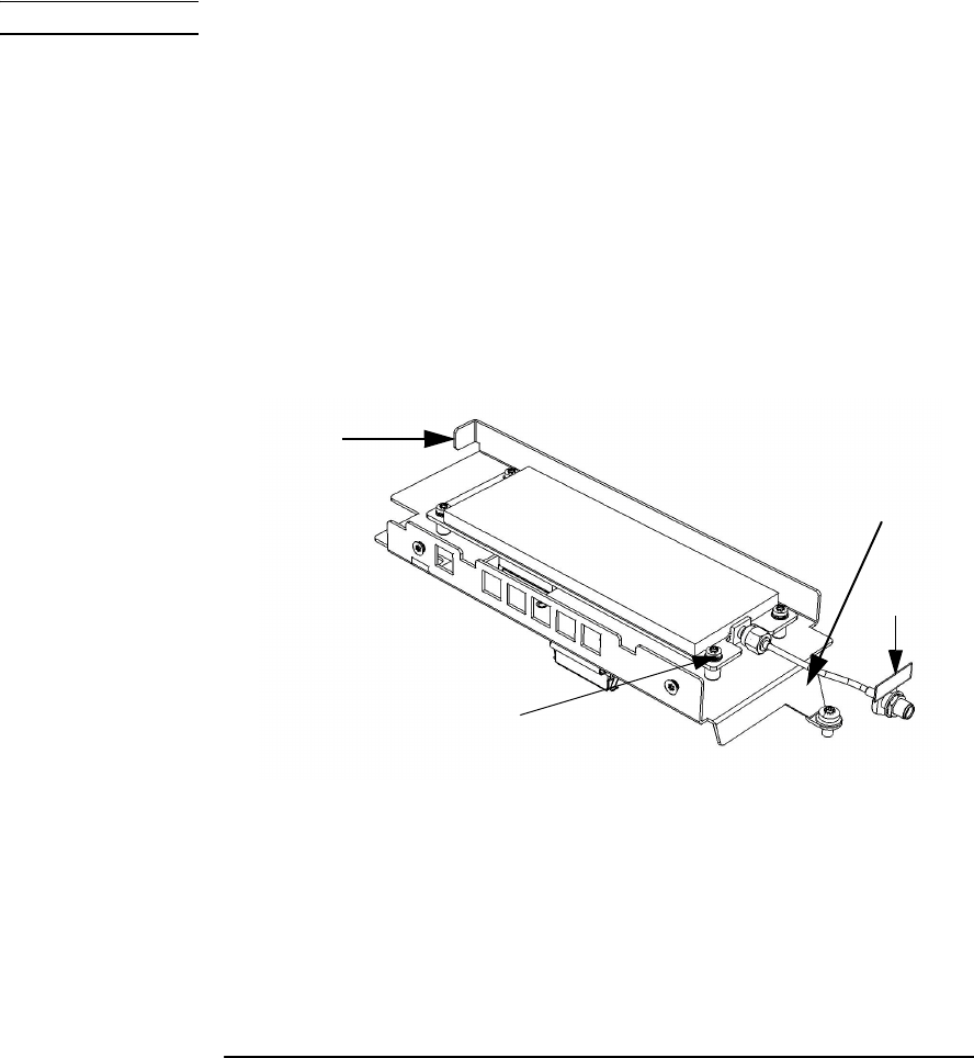
NOTE Refer as necessary to Figure 4-21.
– If Option 115 is being installed, insert and tighten the two
supplied standoffs (using a 1/4" spintite) in the two middle
holes closest to the front flange of the Channel 2 assembly
(Rear Panel Option 203 only).
– Position the printed circuit board over the aluminum
bracket so that the SMA edge connector is pointed toward
the rear flange (with the hole) and sits on top of the
standoffs.
– Install 4 (Option 106) or 6 (Option 115) T10 TORX screws to
secure the PC board to the aluminum deck.
Figure 4-21. 53220A/53230A Rear Panel Option 106/203.
Front
Flange
Rear
Flange
Label
T10
TORX
Screws