
Specifications


Table Of Contents
- Agilent 53210A/53220A/53230A 350 MHz Universal Frequency Counter/ Timer
- Assembly Level Service Guide
- Performance Tests
- Introduction
- Power-On Test
- Self-Test (Q)
- Agilent 53210A/53220A/53230A Operational Verification
- Agilent 53210A/53220A/53230A Complete Performance Tests
- Test 1: (Q) Absolute Time Base
- Test 2: (Q) Frequency Accuracy - Channels 1 and 2
- Test 3: Single Period
- Test 4: (Q) Pulse Width
- Test 5: (Q) Time Interval
- Test 6a: (Q) Frequency Accuracy - Channel 2/3, Option 106 (6 GHz Microwave Channel)
- Test 6b: (Q) Frequency Accuracy - Channel 2/3, Option 115 (15 GHz Microwave Channel)
- Test 7a: (Q) Pulse Burst Frequency - 53230A Channel 3 Option 150 With Option 106
- Test 7c: (Q) Pulse Burst Frequency - 53230A Channel 3 Option 150 With Option 115
- Agilent 53210A/53220A/53230A Operational Verification and Performance Test Record
- Agilent 53210A/53220A/53230A Performance Test Record (Tests 1 to 7)
- Service
- Introduction
- Returning the Instrument to Agilent Technologies for Service
- About the Agilent 53210A/53220A/53230A Calibration Menu
- The Agilent 53210A/53220A/53230A Calibration Procedures
- Equipment Required
- Determine the Counter Firmware Version
- Calibration Cycle
- Calibration String:
- Internal Reference Oscillator Calibration
- Summary of Oscillator Calibration Procedure:
- Remote Oscillator Calibration Summary:
- Voltage Calibration (Internal DACs)
- Option 106 Microwave Channel Frequency Calibration
- Option 115 Microwave Channel Frequency Calibration
- Internal Auto-Calibration
- To View the Calibration Count
- Resetting the Security Code to a Null
- Pre-Troubleshooting Information
- Troubleshooting the Counter
- Unit is Inoperative
- Unit Fails Self-Test
- Power Supply Check
- Checking the Battery and Battery Charger
- Battery Operation
- Preliminary Steps
- Testing the battery
- Normal Battery Operation
- When the battery is enabled and the counter is not connected to AC power, the battery is discharged at approximately 30% of full initial capacity per day. When the battery is disabled and not connected to AC power, the battery is discharged at approx...
- Remote Battery Commands
- Performing The Counter Self-Test
- To Determine the Counter Firmware Version
- Reseat the Boards
- Re-Run the Counter Self Test
- Error Messages
- Replacing Assemblies
- Introduction
- Tools Required
- To Remove the Cover and Rear Bezel
- To Remove the Internal DC Battery Assembly (Option 300)
- To Remove the GPIB Assembly
- To Remove a 6.0 GHz or 15.0 GHz Microwave Channel Assembly (Options 106/115)
- To Remove the Processor Board
- To Remove the Front Panel Assembly
- To Remove the Motherboard
- To Remove the AC Power Supply Assembly
- Retrofitting Options
- Introduction
- To Retrofit Ultra-High Stability Timebase (Option 010)
- To Retrofit the GPIB Connector
- To Retrofit the Internal Battery DC Power (Option 300)
- To Retrofit the 53210A (Channel 1) or 53220A/53230A (Channels 1/2) Rear Panel Inputs (Option 201)
- To Retrofit the 53210A Channel 2 Front Panel Input (Option 106 or Option 115, plus Front Panel Option 202)
- To Retrofit the 53210A Channel 2 Rear Panel Input, 6.0 GHz (Option 106) or 15.0 GHz (Option 115) plus Rear Panel Option 203
- To Retrofit the 53220A/53230A Channel 3 Input, 6.0 GHz (Option 106) or 15.0 GHz (Option 115) plus Front Panel Option 202
- To Retrofit the 53220A/53230A Channel 3 Input, 6.0 GHz (Option 106) or 15.0 GHz (Option 115) plus Rear Panel Option 203
- To Retrofit Option 150 (Pulse Microwave Measurements) for the 53230A
- Replaceable Parts
- Backdating
Chapter 4 Retrofitting Options
To Retrofit the 53210A Channel 2 Front Panel Input (Option 106 or
Option 115, plus Front Panel Option 202)
208 Assembly-Level Service Guide
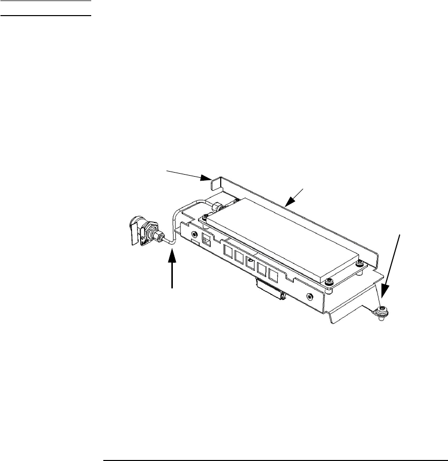
6 Assemble the parts in the Option 106/115 package as follows:
NOTE Refer as necessary to Figure 4-8.
– If Option 115 is being installed, insert and tighten the two
supplied standoffs (using a 1/4" spintite) in the two middle
holes closest to the rear flange of the Channel 2 assembly
(Front Panel Option 202 only).
– Position the PC board over the aluminum bracket so that
the SMA edge connector is pointed toward the front flange
(without the hole) and sits on top of the standoffs.
– Install 4 (Option 106) or 6 (Option 115) T10 TORX screws to
secure the PC board to the aluminum deck.
Figure 4-8. 53210A Channel 2 Front Panel Option 106/202
Rear
Flange
Aluminum Deck
Semi-Rigid
Cable Position
Front
Flange