
Specifications


Table Of Contents
- Agilent 53210A/53220A/53230A 350 MHz Universal Frequency Counter/ Timer
- Assembly Level Service Guide
- Performance Tests
- Introduction
- Power-On Test
- Self-Test (Q)
- Agilent 53210A/53220A/53230A Operational Verification
- Agilent 53210A/53220A/53230A Complete Performance Tests
- Test 1: (Q) Absolute Time Base
- Test 2: (Q) Frequency Accuracy - Channels 1 and 2
- Test 3: Single Period
- Test 4: (Q) Pulse Width
- Test 5: (Q) Time Interval
- Test 6a: (Q) Frequency Accuracy - Channel 2/3, Option 106 (6 GHz Microwave Channel)
- Test 6b: (Q) Frequency Accuracy - Channel 2/3, Option 115 (15 GHz Microwave Channel)
- Test 7a: (Q) Pulse Burst Frequency - 53230A Channel 3 Option 150 With Option 106
- Test 7c: (Q) Pulse Burst Frequency - 53230A Channel 3 Option 150 With Option 115
- Agilent 53210A/53220A/53230A Operational Verification and Performance Test Record
- Agilent 53210A/53220A/53230A Performance Test Record (Tests 1 to 7)
- Service
- Introduction
- Returning the Instrument to Agilent Technologies for Service
- About the Agilent 53210A/53220A/53230A Calibration Menu
- The Agilent 53210A/53220A/53230A Calibration Procedures
- Equipment Required
- Determine the Counter Firmware Version
- Calibration Cycle
- Calibration String:
- Internal Reference Oscillator Calibration
- Summary of Oscillator Calibration Procedure:
- Remote Oscillator Calibration Summary:
- Voltage Calibration (Internal DACs)
- Option 106 Microwave Channel Frequency Calibration
- Option 115 Microwave Channel Frequency Calibration
- Internal Auto-Calibration
- To View the Calibration Count
- Resetting the Security Code to a Null
- Pre-Troubleshooting Information
- Troubleshooting the Counter
- Unit is Inoperative
- Unit Fails Self-Test
- Power Supply Check
- Checking the Battery and Battery Charger
- Battery Operation
- Preliminary Steps
- Testing the battery
- Normal Battery Operation
- When the battery is enabled and the counter is not connected to AC power, the battery is discharged at approximately 30% of full initial capacity per day. When the battery is disabled and not connected to AC power, the battery is discharged at approx...
- Remote Battery Commands
- Performing The Counter Self-Test
- To Determine the Counter Firmware Version
- Reseat the Boards
- Re-Run the Counter Self Test
- Error Messages
- Replacing Assemblies
- Introduction
- Tools Required
- To Remove the Cover and Rear Bezel
- To Remove the Internal DC Battery Assembly (Option 300)
- To Remove the GPIB Assembly
- To Remove a 6.0 GHz or 15.0 GHz Microwave Channel Assembly (Options 106/115)
- To Remove the Processor Board
- To Remove the Front Panel Assembly
- To Remove the Motherboard
- To Remove the AC Power Supply Assembly
- Retrofitting Options
- Introduction
- To Retrofit Ultra-High Stability Timebase (Option 010)
- To Retrofit the GPIB Connector
- To Retrofit the Internal Battery DC Power (Option 300)
- To Retrofit the 53210A (Channel 1) or 53220A/53230A (Channels 1/2) Rear Panel Inputs (Option 201)
- To Retrofit the 53210A Channel 2 Front Panel Input (Option 106 or Option 115, plus Front Panel Option 202)
- To Retrofit the 53210A Channel 2 Rear Panel Input, 6.0 GHz (Option 106) or 15.0 GHz (Option 115) plus Rear Panel Option 203
- To Retrofit the 53220A/53230A Channel 3 Input, 6.0 GHz (Option 106) or 15.0 GHz (Option 115) plus Front Panel Option 202
- To Retrofit the 53220A/53230A Channel 3 Input, 6.0 GHz (Option 106) or 15.0 GHz (Option 115) plus Rear Panel Option 203
- To Retrofit Option 150 (Pulse Microwave Measurements) for the 53230A
- Replaceable Parts
- Backdating
Chapter 2 Service
Pre-Troubleshooting Information
Assembly-Level Service Guide 143
NOTE Any maintenance and repair of the opened instrument under
voltage should be avoided as much as possible and, if necessary,
should be carried out only by a skilled person who is aware of the
hazards involved (for example, fire and electric shock).
Recommended Test Equipment
NOTE Test equipment recommended for testing and troubleshooting the
Agilent 53210A/53220A/53230A Counters is listed below.
NOTE Substitute equipment may be used if it meets or exceeds the
required characteristics listed in Table 2-4.
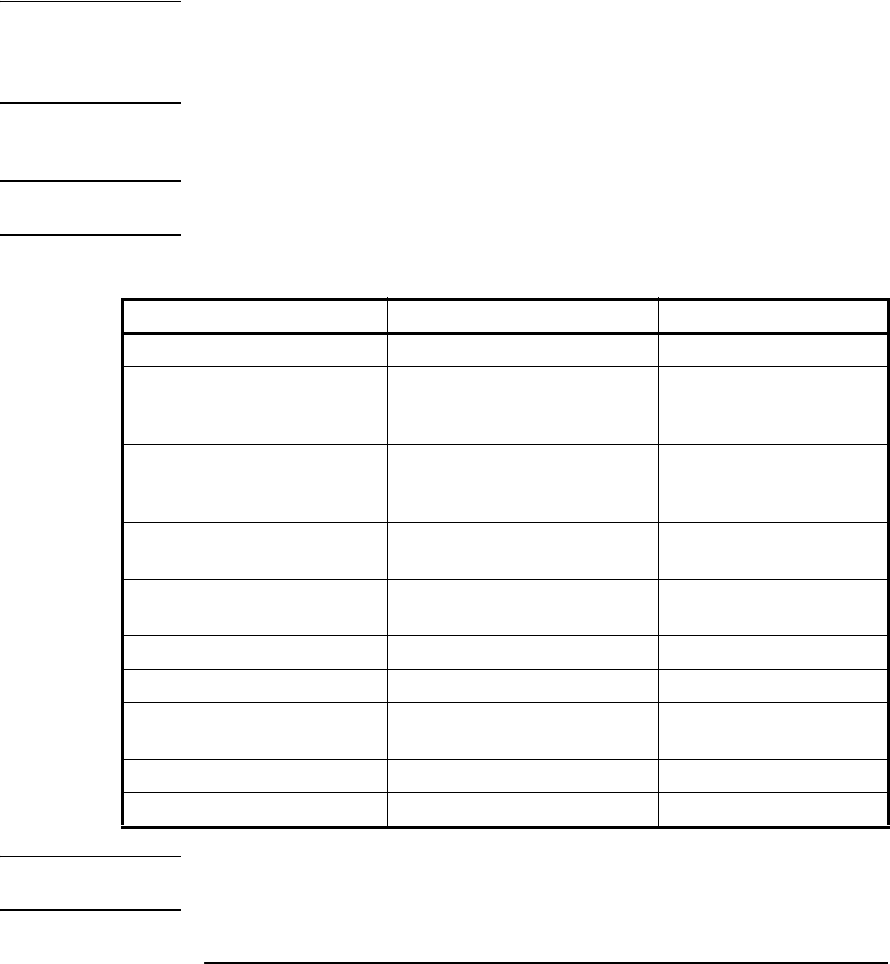
Table 2-4. Recommended Equipment For Test and Troubleshooting
Instrument Required Characteristics Recommended Model
Microwave Signal Generator 100 MHz to 15 GHz Agilent E8257D-520-UNW
RF Signal Generator 10 MHz ± 2.000E-12 Stanford Research
Systems CG635 or
equivalent
Primary Frequency Standard
(10 MHz House Standard)
Absolute accuracy >1 x 10
-10
Stanford Research
Systems FS725 Rubidium
Timebase
DC Power Supply Adjustable to ± 5.000V Agilent 6234A or
equivalent
Digital Multimeter (DMM) Microvolt accuracy Agilent 34410A or
equivalent
Type N-to-BNC Connector Agilent 1250-0780
BNC-to-Dual Banana Plug BNC(f) to dual banana plug(m) Agilent E9637A
50 Ohm Coaxial Cable with
BNC connectors
BNC(m) to BNC(m), 48 inches Agilent 10503A
3.5mm cables DC-18 GHz Agilent 11500E
Coaxial BNC Tee Connector 1250-0781