
Instruction manual


146 Chapter 6
Calibration and Compensation
How to Define Calibration Kit
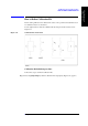
Figure 6-18 Calibration kit setup window
Step 2. Specify the table number to define a calibration kit by following the description in “How to
specify table number for setup” on page 104.
Step 3. Select the type of calibration kit (7-mm Standard or User Defined) from the Cal Kit
selection area in the calibration kit setup display.
If you have selected “7-mm Standard,” the initial value of the 7-mm calibration kit will be
used as the defined calibration kit. No further setting is required.
NOTE When you want to used the Agilent 16195B 7-mm calibration kit, select “7-mm
Standard.”
If you have selected “User Defined,” continue with the following steps:
Step 4. If you want to use the same definition for all measurement points in the measurement point
table, click the
Fixed Model button to attach a check mark (√).
If you have selected “Fixed Model,” set the calibration kit definition for measurement
point number 1. For other measurement points, the same definition as that of measurement
point number 1 is automatically entered.
Step 5. Select the circuit model to define load from Rs-Ls, Ls-Q and Cp-D.
Step 6. Enter open/short/load definitions for each measurement point.
Step 7. Enter the DC open/short/load definitions.
Step 8. When you want to use a calibration kit other than the 7-mm calibration kit, you may have
to set the offset delay. If so, enter each value for offset delay open/short/load.
NOTE The offset delay value is described in the Operation Manual of the calibration kit. Please
refer to this manual.