
Technical data


120 4000 X-Series Oscilloscopes Advanced Training Guide
4 Serial Bus Decoding & Triggering, Search & Navigation, and Segmented Acquisition Labs
19 Tap the Bus Config softkey; then verify that Word Size is set to “8”,
Receiver is set to “8”, Alignment is set to “Standard I
2
S”, WS Low is set to
“Left channel”, SCLK Slope is set “rising edge”.
20 Use your finger to drag the data signals to match the order on the
screen's help image by dragging the digital channel identifiers on the far
left of the display.
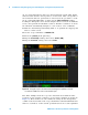
Your scope should now be decoding the left- channel and right- channel
audio data similar to Figure 80. However, the scope is not yet triggering
on these signals. The scope should be randomly auto triggering because
the default trigger condition is to trigger on a rising edge of channel- 1.
But there are no signals present on the channel-1 input. Let’s now set up
the scope to trigger on I
2
S right-channel audio data as the value of the
data increases from
≤ - 10 to ≥ +10 (signed decimal format).
21 Press the [Trigger] front panel key; then select Serial 1 (I
2
S) using the
Trigger Type menu.
22 Tap the Audio Left softkey; then change to Right.
23 Tap the Trigger = softkey; then set it to Increasing value.
Figure 80 Decoding I
2
S signals.