
Technical data


Serial Bus Decoding & Triggering, Search & Navigation, and Segmented Acquisition Labs 4
4000 X-Series Oscilloscopes Advanced Training Guide 103
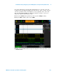
You should now see on your scope’s display what appears to be an
un- triggered display of a digital burst signal similar to Figure 67. Your
scope is actually triggering on random rising edges of channel- 1, which is
the scope’s default trigger condition. But this signal is too complex to
establish a unique trigger point using simple edge triggering. This signal is
a packet/frame of CAN serial bus traffic. Let’s first set up the scope to
intelligently decode this data stream based on the CAN protocol, and then
we will establish a more unique trigger point using CAN triggering.
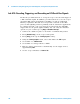
9 Press the [Serial] front panel key.
10 Tap the Mode I
2
C softkey; then select the CAN serial decode.
11 Tap the Signals softkey; then from the Signal menu, select CAN_L.
12 With the Signals menu active, also verify that the input Source is
defined as channel- 1 and the baud rate is set to 125 kb/s (default
conditions).
Figure 67 Capturing a CAN frame using the scope’s Edge triggering mode.