
Programming instructions

Replaceable Parts 85
Chapter 6
Replaceable Parts
Introduction
This Chapter contains the disassembly/assembly procedures for an Agilent
3499A/B/C mainframe, followed by the mechanical and electrical
replaceable parts for the Agilent 3499A/B/C mainframe, and its plug-in
modules. This Chapter contains the following sections:
• Agilent 3499A/B/C Disassembly/Assembly Procedures . . . Page 85
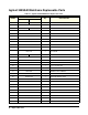
• Agilent 3499A/B Mainframe Replaceable Parts. . . . . . . . . . page 92
• Agilent 34399C Mainframe Replaceable Parts. . . . . . . . . . . page 94
• Plug-in Modules Replaceable Parts . . . . . . . . . . . . . . . . . . . Page 95
Agilent 3499A/B/C Disassembly/Assembly Procedures
WARNING The line power cord and all other interconnections must be
removed before performing any disassembly or assembly
procedures.
Caution The Agilent 3499A/B/C mainframe, as well as the plug-in
modules, are susceptible to static discharges. Use the
anti-static techniques when assemblies are handled or
serviced.
3499A/B
Disassembly
Procedures
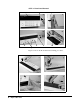
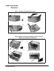
To disassemble an Agilent 3499B half-rack-width mainframe, perform the
following procedures (STEP 1 through STEP 6). For an Agilent 3499A
full-rack width mainframe, the disassembly procedures are the same with
exception of some different replaceable parts, i.e. the Backplane, the
Front-Panel (part), the Rear Bezel, etc.
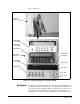
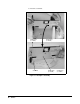
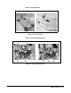
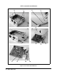
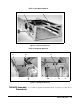
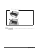
Figure 6-1 through Figure 6-6 demonstrate the disassembly procedures for
an Agilent 3499A/B mainframe. The replaceable parts on it are identified
with a number and listed in Table 6-1 on page 92.
Note The replaceable parts for the Agilent 3499A/B/C plug-in modules are listed
in Table 6-3 on page 95.