
Programming instructions


82 Service
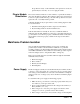
are incorrect, check the cable (03499-61004) and the plug-in
modules. You can perform more tests to further isolate the problem to
the cable, or the particular plug-in module.
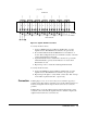
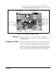
Figure 5-1. Power Supply on the Agilent 3499A/B
Controller Isolating a problem to the Controller board is best accomplished by
substituting a known good board. The Controller is not repairable and should
be replaced if it fails.
Keyboard & Display Problems in the keyboard can be isolated by performing the keyboard test.
No response to a key closure is the typical failure mode of the keyboard. No
response to any key closure would indicate a Controller board failure.
Problems in the display can usually be detected by performing the display
test (i.e. self-test). Typically, a failing display will exhibit missing segments.
Display removal is described in the next Chapter (refer to “Replaceable
J1
J2
J3 (Safety Ground)
03499-6100403499-61007
03499-61002
Fuse 3.15A, 250 VAC
Pin 1 +12V
Pin 2 +5.1V
Pin 3 +5.1V
Pin 4 Return
Pin 5 Return
Pin 6 -12V
Pin 1 AC Line
Pin 2 AC Neutral