
Programming instructions


Service 81
the problem is mostly on the mainframe; if the problem is solved, the
problem may be caused by one or more plug-in module.
Plug-in Module
Substitution
The easiest and fastest method to isolate a failure to a particular assembly is
the board substitution technique. The technique calls for the suspected bad
board to be replaced with a known good board. If the problem is solved, the
replaced board or assembly had the problem.
A limited substitution may be performed to isolate a faulty plug-in module.
To use this method:
1. Determine which plug-in module is suspected of the failure;
2. Try the failing module in another mainframe slot.
If the module functions normally in other slot, a mainframe failure is
indicated; if the module still fails, try a known good module. If the known
good module does not function properly, a mainframe failure is indicated; if
the module does function properly, a failure in the suspected module is
indicated.
Mainframe Problem Isolation
Once an Agilent 3499A/B/C mainframe is suspected of a failure, the
problem may be further isolated within the mainframe to a particular
assembly. Isolating a problem within a mainframe requires that the Agilent
3499A/B/C mainframe be disassembled. A disassembly procedure is given
in the next Chapter (refer to “Replaceable Parts” on Page 85).
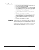
There are four main electronic assemblies within an Agilent 3499A/B/C
mainframe. These include:
1. The Power Supply;
2. The Controller;
3. The Keyboard & Display;
4. The Backplane.
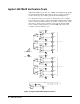
Power Supply The Power Supply assembly is located behind the keyboard. There are three
connectors on it: J1 through J3. J1 is connected to the ac power line and J3
is the safety ground terminal. J2 is connected to the mainframe’s backplane,
which provides a set of voltages (dc) to the Controller board and the plug-in
modules.
To determine if the power supply is functioning properly:
1. Make sure the ac power line are connected properly and the fuse (3.15
A @ 250 V ac) on the pc board is well;
2. Power on the instrument and measure the voltage between Pin 4 (or
Pin 5) and Pin 1 (or 2, 3, 6);
3. If the voltages are correct, the power supply does function; if the
voltage is not correct, a problem exists in this assembly.
4. If the voltages on the J2 are correct, but the voltages on the backplane