
Programming instructions


Verification Tests 77
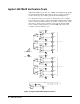
Test Procedure Before testing the Agilent N2280A/81A/82A Optical Switch Module, the
user should have an Optical Multimeter in hand. When testing, the two
Optical probes of the Optical Multimeter should be connected to the two
end-connectors of one channel of the specific Optical Switch, then execute
closing and opening commands on it , you can find whether this channel is
normal or not via the optical multimeter’s display.
To verify that the optical switches in each group are functioning:
1. Plug the Optical Module into a 3499A/B/C mainframe.
2. Connect the Optical Multimeter’s two optical probes to the COMx and
CHxn (‘x’ is the Optical Switch number in the same module, and ‘n’ is the
channel number in the same Optical Switch) of the Optical Switch which is
under testing.
3. Power on the 3499A/B/C mainframe, and execute Opening and closing
command on this channel to see if it is operated correctly.
4. Perform step 2 and 3 on next channel of the same Optical Switch until all
channels of it is tested.
5. Perform step 2, 3, and 4 on next Optical Switch in the same module.
Correction If the channel under testing does not function in the step 3 above, a problem
exists either in the Optical Switch or in the Controller board of this module.
Using a normal Optical Switch to substitute the current one, then perform
the steps listed above. If the problem still exists, this demonstrates the
Controller board is malfunctioning. If the problem disappeared, this
demonstrates the Optical Switch is malfunctioning. Thus the problem is
solved by substituting the Controller board or the Optical Switch.