
Programming instructions


Verification Tests 73
properly.
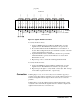
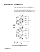
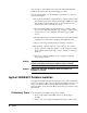
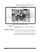
Figure 4-6. Agilent 44477A Test Fixture
To Verify the NO Contacts:
1. Connect a Multimeter between TP1 (C) & TP2 (NO), reset the
Agilent 44477A. The Multimeter should show an open circuit;
2. Close Channel 00 and check the Multimeter for an indication of
closure. This reading will be the closed channel resistance of the NO
contact and should be less than 1Ω;
3. Open Channel 00 and close Channel 01, check for an open circuit
when Channel 00 is opened, and an indication of closure when
Channel 01 is closed;
4. Repeat Steps 2 & 3 to check the remaining Channels 02-06.
To Verify the NC Contacts:
5. Connect the Multimeter between TP1 (C) & TP3 (NC), reset the
Agilent 44477A. The Multimeter should show an open circuit;
6. Repeat Steps 2 through 4 to verify the NC contacts (the “NO” in Steps
2-4 should be replaced with “NC”, respectively).
Correction If during Steps 1 & 5, one or more relays does not function properly, a
problem exists either in the Controller board or in the Agilent 44477A, use
a functional Agilent 44477A and perform the same tests to isolate the
problem.
If during Steps 3 & 6, the Agilent 44477A is functioning but the contact
resistance is more than 1Ω, the Agilent 44477A is defective. Replace the
Agilent 44477A with a new one in this case.
NO
C
NC
NO
C
NC
NO
C
NC
NO
C
NC
NO
C
NC
NO
C
NC
NO
C
NC
CH01
CH00
CH02
CH03
CH04
CH05
CH06
T
O
44477A
WIRING
TERMINA
L
BLOCK
TEST FIXTURE