
Programming instructions

72 Verification Tests
4. Repeat Steps 2 & 3 to verify the other channels;
5. Close all the channels on the Agilent 4476A/B;
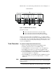
6. Verify continuity between the Channel 00 center conductor of the
common port and center conductor of port 2. For an Agilent 44476B,
you must determine which ports should have continuity for Channel
00 and verify it;
7. Verify there is no continuity between the common port and port 1 of
channel 00. For the Agilent 44476B, you must determine which ports
should not have continuity and verify they do not;
8. Repeat Steps 6 & 7 to verify other channels.
Correction If a Microwave Switch does not function properly, you must determine if the
problem is caused by the drive circuity or drive relays K901, K902, or K903.
Use another same functional Microwave Switch and perform the same tests
as described above to isolate the problem.
The three Microwave Switches are replaceable parts, if any one of them is
defective, replace it with a new one. If the drive circuity or drive relays are
defective, replace the Agilent 44476A/B with a new one (with the exception
of the Microwave Switches if they are functioning).
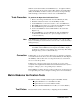
Agilent N2276A/B Verification Tests
Since Agilent N2276A/B has similar style with 44476A/B, please refer to
Agilent 44476A/B’s Verification Tests.
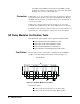
Agilent 44477A Verification Tests
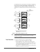
Agilent 44477A contains seven independent, single-pole double-throw
(SPDT) Form C relays. When a channel is open, the normally closed (NC)
will connect to the common (C). When a channel is closed, the normally
open (NO) will connect to the common (C).
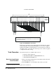
Test Fixture A test fixture can be configured by connecting all relay commons (C)
together at TP1, all normally open (NO) contacts at TP2 and all normally
closed (NC) contacts together at TP3, with an Agilent 44487A screw
terminal block.
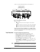
Tests Procedure To verify that all relays are functioning properly, you must:
a. Verify that each relay can close the normally open (NO) contact;
b. Verify that each relay’s normally closed (NC) contact operates