
Programming instructions

Verification Tests 71
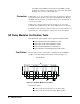
Coaxial Switches; these coaxial switches come in 3/4/5-port configurations.
To verify that the 33311B Coaxial Switches on the Agilent 44476A (or the
switches you provide on the Agilent 44476B) are functioning, verify
continuity between the common port and the port connected to it. Also,
verify there is no continuity between the common port and any unconnected
ports.
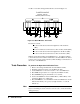
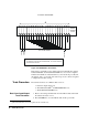
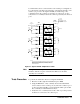
Figure 4-5. Agilent 44476A Simplified Schematic
Note The Agilent 44476B simplified schematic is the same as the Agilent
44476A’s, with the exception of that the three Microwave modules
(33311B) are not installed.
Tests Procedure To perform the Verification Tests for an Agilent 44476A/B:
1. Reset the module (Agilent 44476A/B) and press Mon;
2. Using the Multimeter, verify continuity between the Channel 00
center conductor of the common port (C) and center conductor port 1
(1). For an Agilent 44476B, you must determine which ports should
have continuity for Channel 00 and verify it;
3. Verify there is no continuity between the common port and ports that
should not be connected to the common port;
DRIVE
JUMPERS
FORM C
DRIVE RELAYS
+5V
L901
C906
+5 TO DRIVE JUMPERS (YEL)
RELAY
K901
COM
NO
NC
+5
1
2
3
ORG
YEL
ORG
W1
CHANNEL 00
50
Ω
50
Ω
33311B
2
C
1
2
C
1
1
C
2
NO
C
NC
RELAY
K903
COM
NO
NC
+5
1
2
3
ORG
YEL
ORG
W3
CHANNEL 02
50
Ω
50
Ω
33311B
2
C
1
2
C
1
1
C
2
NO
C
NC
RELAY
K902
COM
NO
NC
+5
1
2
3
ORG
YEL
ORG
W2
CHANNEL 01
50
Ω
50
Ω
33311B
2
C
1
2
C
1
1
C
2
NO
C
NC
MODULE *
PANEL
DESIGNATORS
1 = PORT 1
2 = PORT 2
NO = NORMALLY OPEN
NC = NORMALLY CLOSE
D
C = COMMON
* NOTE :
TERMINAL DESIGNATIONS INSIDE THE DASHED BOXES REFER TO THE
33311B ONLY. MODULE PANEL DESIGNATORS OUTSIDE THE DASHED
BOXES ARE THOSE SILKSCREENED ON THE 44476A PANEL. ANY
REFERENCE IN THIS MANUAL TO A PORT REFERS TO THE MODULE
PANEL DESIGNATORS.
P
I
V
O
T
A
R
M
A
T
U
R
E
P
I
V
O
T
A
R
M
A
T
U
R
E
P
I
V
O
T
A
R
M
A
T
U
R
E