
Programming instructions

Verification Tests 69
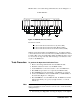
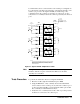
module should be input (DIN). Press Mon, the display should be
“DIN 11111111 snn” or “DIN 255 snn”, where s = slot number, and
nn is the related port number;
3. Write a binary 10101010 to any one of the 8-bit ports (in order to
open every other line) and verify the data has been transferred to all
the other ports.
Take an Agilent N2263A for example, if a data (10101010) has been
written to the port s02, this data should be transferred to other ports
s00, s01 and s03. When these ports (s00, s01 & s03) are monitored,
the display should be 10101010 (binary) or 170 (decimal). If it does
not, a problem exists on this DIO module.
Note You can write any other data to one port to verify the data lines.
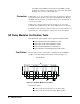
Chan Closed and
PFLG/EXT INC Tests
Procedure
1. Reset the DIO module and create a scan list including all the bits on
this module;
2. Press Step. If the CHAN CLOSED (Agilent 44474A only) and/or
PFLG/EXT INC lines are functioning, the Agilent 3499A/B/C will
begin stepping through the scan list, opening each data line as it
closes the previous line. This will be shown on the Agilent
3499A/B/C’s display as the first 8-bit port being successively
decreased by the binary weighted value of each data line. In other
words, the display will start with the value of 255, step to 254 (binary
1), step to 253 (binary 2), step to 251 (binary 4), step to 247 (binary
8), step to 239 (binary 16), step to 223 (binary 32), step to 191 (binary
64) and finally, step to 127 (binary 128). When all eight data lines in
this port have been stepped through, the port will reset to 255 and the
process will repeat with the second 8-bit port, and so on.
If the scan list will not automatically advance as described above, the CHAN
CLOSED line, the PFLG/EXT INC line, or both are malfunctioning.
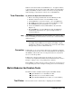
IO/WR and PCTL/RD
Tests Procedure
1. Reset the DIO module;
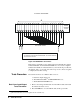
2. Connect the Multimeter between the GND and the PCTL/RD (or
IO/WR) terminals on the test fixture (Figure 4-4 on Page 68) to
measure dc voltage. The PCTL/RD (or IO/WR) line should be in the
high state (between +2.4 V dc and +5 Vdc);
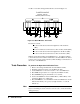
3. Change the polarities of the IO/WR and PCTL/RD to negative
(NEG), and write a data to any one of the 8-bit ports on the DIO
module (for more instructions, refer to “Front-Panel Operation” on
Page 31);
4. Measure the voltage between the GND and the IO/WR (or PCTL/RD)
terminals. The IO/WR (or PCTL/RD) line should be in the low state
(between 0 Vdc and +0.4 V dc).
If either or both control lines failed to achieve either or both states, a
problem exists in either the mainframe Controller board or the plug-in DIO
module. You can isolate the problem by testing the same items described
above with another (same type) functional DIO module.