
Programming instructions

64 Verification Tests
3499A/B/C and the Multimeter. The Agilent 3499A/B/C’s display
should show a number corresponding to the closed relay. The clumsy
damaged relay(s) can be isolated in this way.
Correction If during Step 8, one or more relays did not close as described, a problem
exists either in the Controller board or the related MUX module. Replace
this MUX with another same one and perform the tests as described above
to isolate the problem.
If during step 8, the appropriate relays closed, but one or more of the
resistances were higher than 1 , the corresponding relay(s) are defective.
If a MUX module is defective, replace it with a new one (the relays are not
replaceable parts, refer to Chapter 6 on Page 85 for more information).
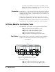
GP Relay Modules Verification Tests
The GP Relay modules available with an Agilent 3499A/B/C include:
Agilent N2261A 40-channel GP Relay module;
Agilent 44471A 10-channel GP Relay module;
Agilent 44471D 20-channel GP Relay module;
Agilent N2264A Multifunction (GP function);
Agilent N2267A 8-channel High Current GP module.
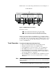
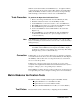
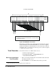
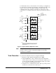
Test Fixture The test fixture can be constructed by configuring the related GP Relay
module’s removable wiring terminal block as shown in Figure 4-2.
Figure 4-2. GP Relay Modules Test Fixture
The fixture contains:
A short circuit between all of the low (L) lines (TP1);
A short circuit between all of the high (H) lines (TP2).
Ω
72
*
35(/$<