
Programming instructions

Verification Tests 63
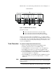
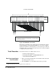
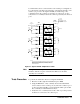
MUX module’s removable wiring terminal block as shown in Figure 4-1.
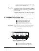
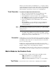
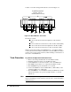
Figure 4-1. MUX Modules Test Fixture
The fixture contains:
A short circuit between all of the low (L) lines (TP1);
A short circuit between all of the high (H) lines (TP2);
A short circuit between the shorted common lines (COM).
With the test fixture installed, and a Multimeter (i.e. an Agilent 34401A)
connected between the shorted common lines (COM) and either the shorted
low lines (TP1) or the shorted high lines (TP2), the MUX module is tested
by successively closing each relay while checking for an indication of the
closure on the Multimeter.
Tests Procedure To perform the Operation Verification Tests:
1. Remove the wiring terminal block from the MUX module;
2. Install the related test fixture onto the MUX module;
3. Set the Multimeter to measure resistance. “Zero” the Multimeter;
4. Press Mon and specify the slot occupied by the MUX module;
5. Press S.LIST and specify all channels on the MUX to be scanned;
6. Connect the Multimeter between COM & TP1 (or COM & TP2) on
the test fixture (Figure 4-1 on Page 63);
7. Press Card Reset to reset the MUX module, the Multimeter should
indicate that all relays are open (very high resistance or overload
indication);
Note If the Multimeter is indicating a very low resistance, one or more of the
relays is remaining closed. You need to do more tests to isolate the clumsy
damaged relay(s).
8. Successively press Step while observing the displays on the Agilent
7208;02'8/(