
Programming instructions

Front-Panel Operation 35
digital I/O port, or an entire plug-in module. Agilent 3499A/B/C provides
you the ability to achieve the above.
1. Press Mon, the MON annunciator lights up;
2. Select the slot or the channel/port to be monitored;
3. Press Enter to display the next part if necessary;
4. Press Mon again to exit the monitoring state, the MON annunciator
turns off.
Note The built-in digital I/O can be monitored either as individual bit channels
(091-094) or as a 4-bit port (090).
Note For MUX modules and GP Relay modules, 10 channels can be displayed at
one time; for matrix modules, one ROW or one Column can be displayed at
one time; for digital I/O modules, two 8-bit ports can be displayed at one
time. For multifunction modules, the first function on the module is
displayed, then the next.
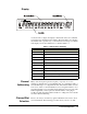
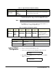
Table 3-2. Display on Monitoring Mode
Display Description
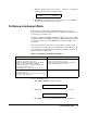
The display for a multiplexer or a GP relay module. This display indicates that
the monitored module is in Slot 2 and channels 10, 16, and 19 are closed.
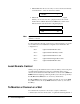
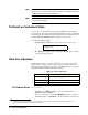
The display for a matrix module. The top is the row information, indicating that
the relays on Row 3, Columns 1, 3, 6 and 7 of the module (in Slot 3) are
closed. The lower display is the column information, indicating that relays on
column 3, row 0 and 3 are closed.
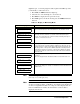
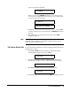
The display for a digital I/O module. The first 2 digits on the left (“00” in this
case) represents the “L” 8-bit port address. Adding one to this value, the “H”
8-bit port address is obtained. Data with a trailing decimal point indicates that
the last operation on that port was a WRITE, data without a trailing decimal
point indicates that the last operation on that port was a READ. This display
shows that the data last read from Port 401 is 255 and the data last written to
Port 400 is 254.
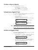
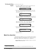
The top display is for the built-in digital I/O Port 090 and the data from the last
operation.
The lower display indicates that data last written to the bit channel 091 is 0.
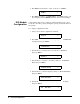
For a multifunction module, the first function on the module is displayed, then
the next. This display is an example of a multifunction module with matrix and
DIO functions.
1:0, , , , , ,6, , ,9, 2
ROW 3: ,1, ,3, , ,6,7 3
0; , ,3,COL 3, 3
00:H255 L254. 4
DIO 12 090
DOUT 0 091
ROW 0: ,1, ,3, 5
00:H255 L254. 5