
Programming instructions

Front-Panel Operation 33
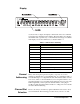
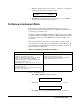
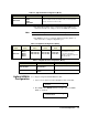
Display
As shown in above figure, the display is divided into three areas. Channel
area displays the channel/port/slot number. The main display area displays
the channel status (open/closed), or other information messages. Around the
main display area are the annunciators, as listed in Table 3-1.
Channel
Addressing
Many of the front-panel operations require you specify one or more
channels. A channel refers to an individual relay on a switching module, or
an individual bit/port on a digital I/O module. The channel address is in the
form of snn, where s is the Slot Number (1-5 for an Agilent 3499A, 1-2 for
an Agilent 3499B, 1-9 for an Agilent 3499C and Slot 0 reserves for the 4-bit
built-in digital I/O), and nn represents channel number on the plug-in
modules (module dependent). Refer to Table 2-1 on Page 24 for more details
about the channel addressing.
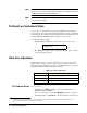
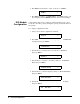
Channel/Slot
Selection
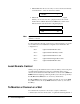
The two arrow keys (<= and =>) together with the knob are used to select
slots and channels. The following procedure shows you how to do that.
,
.
.
,
.
.
,
.
.
,
.
.
,
.
.
,
.
.
,
.
.
,
.
.
,
.
.
,
.
.
,
.
.
,
.
.
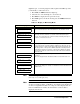
Table 3-1. Annunciators Summary
Annunciator Indication
SCAN
Scan is initiated.
MON
Instrument is in monitor mode.
VIEW
Scan list, errors or relay cycle counts are being viewed.
CONFIG
Any configuration key has been pressed.
*
Instrument is advancing a scan step.
ADRS
Instrument is addressed to listen or talk over the remote interface.
RMT
Instrument is in remote mode.
ERROR
Error queue is not empty.
EXT
Scan is waiting for external trigger source.
SHIFT
Shift key has been pressed.