
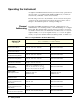
Programming instructions

28 Getting Started
5. Agilent N2265A Multifunction Module;
6. Agilent N2266A 40-channel 2-Wire MUX Module;
7. Agilent N2267A 8-channel High Current GP Module;
8. Agilent N2268A 50Ω 3.5GHz Dual 1-to-4 MUX Module;
9. Agilent N2270A 10-Channel High Voltage MUX Module;
10.Agilent N2272A 1GHz RF 1-to-9 MUX Module;
11.Agilent N2276A/B Dual 1-to-6(4) Microwave MUX/Atttenuator
Module (not include Attenuators);
12.Agilent N2280A/81A/82A Optical Switch Modules.
To read out the relay cycles, press View, turn the knob until the “RELAY
CYCLES” is displayed, press Enter to view the relay cycles of the
switching relays. Turn the knob to view all the relay cycles on the plug-in
modules.
Note “N/A” will be displayed a little while if the module does not support relay
cycle count feature.
To View the Errors
The Agilent 3499A/B/C can store up to 10 errors in the error queue. Once
an error occurs, the ERROR annunciator turns on.
To view the errors, press View, turn the knob until “ERROR” is displayed,
press Enter to view the error. Refer to Appendix B “Error Messages”
starting from Page 122 for more error messages.
Note In SCPI mode, the instrument will display “NO ERROR” for a little while,
then return to the upper menu if the error queue is empty. In 3488A mode,
the instrument will display “0000” if no error occurs.
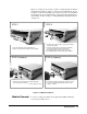
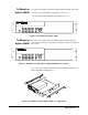
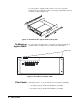
To Rack Mount the Agilent 3499A/B/C
You can mount the Agilent 3499A/B/C mainframes on a standard 19-inch
rack cabinet with the optional rack-mounting kits. The instructions and
mounting hardware are included with each rack-mounting kit.